Wiring
Project Logs
December 28, 2011
A pre-requisite to my recent cockpit locker work was to install the solar panel wiring run from the lazarette, through the port sea locker and into the navigation station area. I also placed a wiring run below the stern chain locker so that wiring could cleanly be passed from starboard to port if required.
A few months ago, I also added conduit through the head that would route electrical wire through the head area and into the v-berth area.
June 17, 2011
I’ve placed two 3/4″ PVC pipes to serve as a route for electrical wires to go through the icebox/wardrobe area. One conduit (placed higher along the hull) will be used to run electrical forward to the v-berth area. The lower conduit will eventually house the transducer and perhaps (and somewhat undesigned) the water line from the tanks as well. I hope to have all the conduit in place in the next few months so that when it comes to wiring, everything is set and ready to go.
The big thing for constructing all of the wire runs will be to preserve the water-tight bulkhead areas that I’ve built. What this means is that anywhere PVC conduit go through a bulkhead, I need to glass the conduit in place on both sides with thickener and pieces of biaxial cloth so that there is no way water can find it’s way into the hole that was cut to allow the PVC to pass through. Once installed, I protect the ends of the pipe so that no errant epoxy will cause trouble with any fittings or final work I do once major construction is complete.
Research
- Volts – refers to the electrical potential of your battery. Put another way, it is the potential difference between two points in a wire – in this case, your battery. (Upgrading the Cruising Sailboat, p. 242)
- Volts – measurement of force. It is what causes the current to flow. Voltage is a measurement of what is called potential. (This Old Boat, p. 262)
- Amps – the amount of electrical current that flows from your battery. Because your battery’s voltage is nearly constant, the current drawn by most appliances also will be nearly constant. Currency is a rate of flow, and therefore it would be incorrect to say “amperes per hour”. This is like saying “knots per hour”…. Remember that a milliamp is 1/1000th of an amp. Thus, 50 milliamps = 0.05 amps. (Upgrading the Cruising Sailboat, p. 242)
- Ampere – commonly shortened to amp, is a measurement of the rate of the flow of electric current. It indicates the number of electrons that pass a point in a given time. …One ampere is equal to a flow of 6,280,000,000,000,000,000 electrons per second. Would you rather say, “5 amps” or “3.4 billion electrons per second”? Amps it is. (This Old Boat, p. 262)
- Watts – term used to rate some electrical items, such as light bulbs. Amps x Volts = watts. Watts / volts = amps. So, if you run a 15-watt fluorescent bulb on a 12v system, you are drawing 1.25 amps (15W / 12V = 1.25A). Amps x hours of operation = total amper-hours. (Upgrading the Cruising Sailboat, p. 242)
- Watts – a measurement of power. The only reason we are interested in electricity is to get it to do work for us. The watt is the rate of doing work. (This Old Boat, p. 262)
- Ohm – Measurement of resistance…Smaller wire inhibits the flow of electrons… (This Old Boat, p. 262)
- Ohm’s Law – current is directly proportional to voltage and inversely proportional to resistance. The equation that expresses this is V = I x R…current is usually our unknown, making the reorganized equation I = V / R. (This Old Boat, p. 262)
- Power Equation – Power is the rate of doing work….Multiplying voltage in volts by current in amps gives us electrical power in watts. The equation for this relationship is P = V x I. You are likely to use the power equation most often to determine current. In this case, the equation becomes I = P / V . It tells us that our 25-watt lamp operating at 12 volts draws a little more than 2 amps (25 / 12) in use, that the brighter illumination of a 50-watt bulbs draws an additional 2 amps (50 / 12) and that a 150-watt SSB transmission draws 12.5 amps (150 / 12). (This Old Boat, p. 262)
- Use a table for measuring the amount of electricity used on board. This way, you can determine more accurately how much electricity you’ll need to run the various electrical gadgets…By listing all your electrical appliances along with their amps and hours of operation, you can estimate your daily usage of electricity. (Upgrading the Cruising Sailboat, p. 241 – 2)
- For an image of the the worksheet to check how much amperage is required, see Upgrading the Cruising Sailboat, Fig. 12-2 ,p. 243
- A passage of just a day or two results in an energy crunch on most modern boats. (Cruising Handbook, p. 86)
- Of course the same power source that lights the cabin can also start the engine, pump the bilge, pressurize the water system, lift the anchor, cool the refrigerator, illuminate channel markers, gauge the depth, transmit your voice tens or hundred of miles, let you “see” through fog, make you visible at night, bring you Beethoven, and tell you exactly where you are. You will no doubt find at least some of these other uses appealing. (This Old Boat, p. 260)
AC System Wiring
- From distribution panel to outlets and hardwired appliances, the same rules expounded earlier for DC wiring apply, including where to route it, how to support it and what wire type and size to use. A prime advantage of the higher voltage of AC is lower amperage for about the same amount of work. A 120-watt appliance operating at 12 volts draws 10 amps, but at 120 volts it just draws 1 amp. With the combination of low current levels and short wire runs, we wouldn’t expect voltage drop to be much of a concern with AC, but it can be….if you expect to run an air conditioner or an AC refrigerator, install wires at least one size larger than the table suggests. A two-size increase is not overkill. If you bundle wires for two or three circuits – not recommended but sometimes nearly unavoidable – their combined potential for heating necessitates wire two sizes larger than normal anyway. Larger wires offer the added benefits of running cooler and giving your system add on capacity. (This Old Boat, p. 307)
- Although the neutral wire in a household AC circuit is connected to the grounding (earth) wire at the main panel box, the neutral is never grounded on a boat (if you don’t know why, you shouldn’t be messing around with wiring). (Cruising Handbook, p. 192)
- By code the hot wire in the AC circuit is black, red, or blue; the neutral wire is always white. it is the black wire, the hot side of the circuit, that should be the most dangerous, but….you cannot be sure which wire is the hot one without testing it.…A wire reversal anywhere between you and the power source will make the wire you expect to be neutral hot. The consequence of this exceedingly common occurrence is that switches and fuses and breakers will be on the wrong leg of the circuit. A switch still turns off the appliance, but it has disconnected the ground, not the power. That means all of the wiring in the appliance is still hot. (This Old Boat, p. 304)
Battery Wiring
- …the cable vaporizes…It is done by wiring one or more pieces of equipment directly to the boat’s batteries without installing a fuse or circuit breaker at the battery positive connection. Every single one of those unfused or unbreakered connections is a cable meltdown waiting to happen. All it takes to set things in motion is a short to ground (earth), such as may occur if the insulation gets damaged or a terminal comes adrift and contacts any grounded object. (Cruising Handbook, p. 174)
- If the boat has an isolated cranking battery, these should be an in-line fuse close to the battery in the cable to the starter motor. To prevent this fuse from blowing under a heavy cranking load (e.g., in cold weather), it should be a slow-blow fuse rated at 150% of the ampacity (the amps rating) of the cranking cables. (Even overrated like this, the fuse still protects against a meltdown if the starter motor or its cables short out.) If the boat has two battery banks, alternated in use, with the cranking circuit coming off whatever bank is in service, the two banks will be wired to a “1,2, Both, Off” switch, with fuses at the batteries in the two feeder cables. The output of the switch will go to the high current bus bar; the cranking circuit will simply be another of the fused circuits coming of the bus bar, with its fuse rated as described previously. (Cruising Handbook, p. 175)
- The high currents passing through battery cables make them particularly liable to generate enough heat to melt solder, and a loose battery cable is singularly dangerous. Never attach cable lugs with solder. Either buy ready-made battery cables, have end fittings crimped on by a cable fabricator, or buy yourself a hammer-blow crimper capable of securing cable lugs. (This Old Boat, p. 276)
- To combine 12-volt batteries into a bank that combines their capacities, you wire them together in parallel….All the positive posts are connected and all the negative posts are connected…has no effect on voltage but it combines their amperages. Wire two 100 Ah, 12-volt batteries in parallel and you create a 200 Ah, 12-volt bank. (This Old Boat, p. 266)
- Components combined in series are linked together like railroad cars. Connecting two batteries in series – the negative post of one of the positive post of the other – combines their voltages….To get a 24-volt bank, you would wire two 12-volt batteries (or banks) in series. Or four 6-volt batteries….connecting batteries in series is likely to be limited to connecting a pair of 6 volt batteries to deliver 12 volts….Batteries wired in series must be identical – same make, model, capacity, and age. If one battery in a series pair fails, you must replace both. (This Old Boat, p. 265)
- …only have to connect the positive wire to the positive battery terminal and the negative wire to the negative battery terminal. Circuits on a boat, at least those you are likely to get involved with are rarely more complicated than this. Of course, you don’t actually connect appliances directly to the battery. Well, sometimes you do. Connecting an automatic bilge pump directly to the battery insures that it will function even when you have turned off the main battery switch. And connecting radio transmitters directly to the battery can maximize transmitting power and eliminate interference from other electrical appliances. (This Old Boat, p. 272)
- You also need to pay attention to the black battery cable bolted to the engine. All engine electrics depend on this cable and its connections to complete the circuit back to the battery. Disconnect this cable and you open all of the engine circuits. If more than one ground cable is bolted to the engine, that typically means the ground from the distribution panel terminates here rather than connecting directly to the negative terminal of the battery. In this case, all your boat’s circuits will depend on the integrity of this connection. Both corrosion and vibration are enemies. Keep this connection bright and tight. Remember to use your multimeter to check for voltage drops on the ground side of circuits as well as the hot side. This can be especially useful on ground return circuits. (This Old Boat, p. 302)
- Most external regulators have outputs that allow you to drive a solenoid that combines the two battery banks during charging and disconnects them afterwards. You can also use battery combiners to achieve the same effect. I would stay away from diode systems because of the voltage losses associated with them. A more elaborate, battery life maximizing solution can be found in the isolator/eliminator manufactured by Ample Power that treats your starter bank as a completely separate bank and charges it accordingly. (http://www.vonwentzel.net/Battery/03.Banks/index.html)
- A CPD (circuit protection device, i.e., fuse or breaker) is required on house battery cables running to your panel. It should be within 7″ of the battery, unless the cable is in a protected channel. I believe there is still no requirement for a CPD on the starter circuit, though some believe it’s not a bad idea. I have one on mine….250A.Re: direct connection to the battery lug, I wouldn’t do that. The fuses are not meant to be flexed. Buy a proper fuseholder…they’re not expensive….and mount it near the battery. Make up a short cable from the fuseholder to the battery. Then, just attach your existing cable to the other end of the fuse. Simple. Troublefree if done properly.There are also fuses which are designed to attach to battery lugs. These are probably OK, though I don’t much like the idea. (http://www.cruisersforum.com/forums/f14/fusing-the-battery-cable-28258.html)
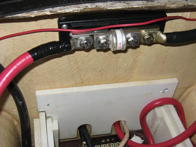
- The pragmatic approach is that installing a fuse is a good thing, regardless of whether you can do it in 7″ or not. You should have one for each bank of batteries, but not necessary for each battery in a bank. There are portions of the ABYC that a lot of people dont agree with, or that are impractical as heck. It’s like any type of regulation, sspecification or code, it’s a generalization that is trying to fit all circumstances… but the real world has a lot of variables….7″ from the battery….It’s tough.. On mine the ANL fuse is actually about 5″ from the battery but for strain relief the cable itself is about 10″-12″ long..Here’s an image: (http://www.cruisersforum.com/forums/f14/fusing-the-battery-cable-28258.html)

MainSail’s battery fuse
- The only type of fuse one should use on the house batteries is a class-T fuse. The reason is that this is the only fuse with a high enough interrupt-rating to handle the short-current from the battery bank. If another type of fuse is used, it could fail to interrupt the circuit (burning up but melting and forming a circuit again). The photo is the class-T fuse on Jedi with a 400A rating on the 1200Ah house battery bank: (http://www.cruisersforum.com/forums/f14/fusing-the-battery-cable-28258.html)

Example of Class-T fuse
- A T-fuse may be a better solution, but it’s not the only solution. “Class T” Fuses are rated to 20,000 Amp Interrupting Capacity (AIC). * Interrupting capacity is the total (fault) current the fuse can interrupt without damage.Higher AIC’s are better; but ABYC only requires up to 5,000 AIC in it’s most stringent case. Accurately calculating the available fault current (dead short) is not a simple task. It’s this available fault current that determines the required interrupting capacity….“ANL” Fuses are rated to 6,000AIC. ABYC requires that large 12 & 24V battery banks, up to 1,100 Cold Cranking Amps (CCA), be rated (Fuse, Cct. Breaker, or Both) to 5,000 AIC. Smaller battery banks require 3,000 AIC or 1,500 AIC (banks under 650 CCA). Terminal Fuses, as offered by Blue Sea Systems are rated 10,000 AIC (@ 14V), which will be more than adequate for large battery banks. (http://www.cruisersforum.com/forums/f14/fusing-the-battery-cable-28258.html)
- Starter batteries are not required to have a fuse and opinions on what’s better differ 50/50. We opted not to have a fuse there. (http://www.cruisersforum.com/forums/f14/fusing-the-battery-cable-28258.html)

Bilge Pump Wiring
- As with all other circuits on a boat, a bilge-pump circuit should be protected at its source. My preference is for a fuse rather than a breaker because it creates less of an opportunity to accidentally turn off the bilge pump when leaving the boat. The fuse should have a rating that does not exceed the current-carrying capability (the ampacity) on the smallest cables in the circuit (usually the cables that come attached to the pump or its float switch). Properly sized, the fuse will prevent the wiring from melting down in the event of a serious short circuit. However, with centrifugal bilge pumps, there is always the risk of a piece of debris jamming the pump impeller, creating what is called a locked rotor state. Given a locked rotor, the current draw of a pump rises dramatically, but not necessarily enough to blow the fuse. The pump may then get hot enough to start a fire…the cumulative resistance of the undersized cable may be enough to limit the current flow on the circuit to a level at which the fuse will not blow. Using a lower rated fuse is not the way to handle this problem because it may result in nuisance blowing; upgrade the cabling instead. Then, given a locked rotor, the cables will pass a current flow that is high enough to blow the fuse, shutting down the circuit. (Cruising Handbook, p. 222)
- …improvement in bilge pumping performance comes from wiring a pump with cables sized to minimize voltage drop. Typically, there is a relatively long cable run from the distribution panel or battery to a bilge pump. For a given size of cable, the longer the cable run, the greater is the cumulative voltage drop. Frequently, the cables are not sized to take this into consideration, and voltage drop ends up around 10% or even higher. What this means is that, given a battery voltage of 12.0 volts (not uncommon), the pump will only be seeing 10.8 volts, which results in a drop in the pumps rated output by as much as 20%. (Cruising Handbook, p. 222)
- Given the inhospitable environment in the bilge, tinned cable is preferred over plain copper, and all connections should be sealed with glue-type heat-shrink tubing to make them as waterproof as possible…when wiring the pump is the importance of ensuring that the pump switch is installed in the positive feed to the pump. The pump itself works as well with the switch in the negative side of the circuit as it does in the positive side. However, if the switch gets installed in the negative side, the bilge pump, and more importantly, any metal through-hulls below the level of the bilge water may suffer from potentially devastating stray-current corrosion. Even if a switch is installed correctly, stray current corrosion will destroy the electrical connections inside the switch and disable the switch if water penetrates the seals. It’s operation should always be checked by lifting the float before leaving a boat. (Cruising Handbook, p. 222)
- Float switches stick. They also fail, which is when you will wish you had [a] manual switch…All it requires is a three-position switch – what is known as a single-pole double throw (SPDT) switch – which has 3 terminals. Flipping the switch lever to the right connects the center terminal to the terminal to the right. Flipping the switch lever to the left connects the center terminal to the left terminal. The middle disconnects all the terminals….Connect the end that is coming from the battery to the switch’s center terminal, and connect the other end to either of the other terminals. When you flip the switch to that side, the pump will run. However, if you really want to energize the pump with the switch in either of the on positions….rather than splice wires, suppose we just put ring terminals on a short length of wire and connect this “jumper” to the left and right terminals. That means that one of these terminals will have connectors under the screw, one on the end of the jumper and the other on the wire leading to the pump. Again, flipping the switch either way runs the pump…Now instead of a wire jumper, suppose we crimp ring terminals onto the two leads from the float switch and connect these to the right and left terminals on the switch. If we flip the switch one way, the current must through the float switch to reach the pump, so the pump will not run until the float switch closes. This would be the normal setting for the switch. Flipping the switch the other way bypasses the float switch to deliver power directly to the pump, giving us a way to run the pump manually. The middle position turns everything off. (This Old Boat, p. 280)
- ….wire it [the high-capacity bilge pump] to a dedicated breaker in the main panel. The breaker can double as the switch, or you can route the hot wire through a separate toggle switch mounted in some prominent location near the companionway….Wiring this pump to the panel allows either of the battery banks to supply the power to run it. (This Old Boat, p. 348)
- If your pump has short leads, you will need to extend them carefully using oversize tinned boat cable; make the connection watertight with adhesive heat-shrink. (This Old Boat, p. 348)
- Connect the relay [cycle counter] to the pump exactly like you would an alarm or a warning light, by connecting one lead to the positive lead from the pump and the other to ground. When the pump is energized by the float switch, the relay closes and the counter advances. An automatic bilge pump with an integral float switch should have a third wire for manual override, which will be energized when the pump runs. Connect the counter (or warning light) to this wire. (This Old Boat, p. 349)
- A buzzer, something that gets your attention but not that the rest of the anchorage, is better for monitoring “normal” bilge pump activity, but a red warning light in the cockpit will be more crew friendly for a boat underway. You can have both (and a counter, all wired in parallel) with a disabling switch in the buzzer circuit to avoid disturbing the off-watch crew. The light in the cockpit will keep the on-watch crew apprised….Knowing about a leak can be more critical than pumping out the accumulation. (This Old Boat, p. 350)
Bonding & Grounding
- See ‘Bonding & Grounding‘ project page.
Bus Bar
- …check the current rating of any high-current bus bars because these too, if overloaded, can get hot and start a fire. Brass often is used as the base material and then maybe tin-, nickel-, or chrome-plated. it is a little-known fact that brass only has 28% of the electrical conductivity of copper; therefore, large bus bars are needed to carry high currents. it is preferable to use tin- or nickel-plated copper, which also does not corrode like brass. (Cruising Handbook, p. 178)
- Stainless steel bolts and washers are almost universally used in marine bus bars. Stainless steel has only 3% of the electrical conductivity of copper – in other words, it is a poor conductorr. (Cruising Handbook, p. 178)
- Any cable terminal bolted down with a stainless steel bolt must be in direct contact with the bus bar to which it is bolted. If a stainless steel washer is allowed to come between a cable terminal and the bus bar, the washer puts a relatively high resistance in the circuit. This resistance not only seriously impairs the performance of the equipment in the circuit, but also creates a lot of heat – more than enough in many high-current circuits to start a fire. Because there is no short circuit, and therefore, no excessively high current flows, a fuse or circuit breaker does not protect against this kind of a fire. (Cruising Handbook, p. 178)
- …if a terminal is only loosely attached to a bus bar (or anything else, for that matter), it tends to arc whenever current flows (i.e., the equipment is turned on). The higher the current flow, the more powerful is the arc and the greater is the risk of starting a fire. Once again, a fuse does nothing to protect against this time of fault. Every connection in a high-current circuit must be well fastened, preferably with a Nylok nut or a similar fastener that will not vibrate loose. (Cruising Handbook, p. 178)
- If the distribution panel cannot accommodate as many circuits as seems necessary, it might be a good idea to add a new bus with additional circuits. To determine whether you will oveloading a circuit, you need to know the total load (in amps) on the circuit, and the wire size (gauge) and the length of those wires. (Upgrading the Cruising Sailboat, p. 278)
Circuits
- Electrical shorts are probably the number-one cause of fires on boats….if you add any circuits to your boat, make sure they are properly protected. (Cruising Handbook, p. 173)
- …some circuits need to bypass the isolation switch so that they can be left “on” when the rest of the boat is shut down. These circuits typically include a bilge pump and any charging devices left on when the boat is not in use (e.g., solar panels, maybe a wind generator, and the inverter if it also doubles as a battery charger); there may also be a carbon monoxide or or propane alarm and DC systems monitoring devices. All except the inverter are wired to a separate auxillary bus bar that is fed by a fused cable into the battery side of the isolation switch. In turn, each circuit is fused at the bus bar. Given the heavy cable likely to be associated with the inverter, it is best wired directly to the terminal on the switch and provided with its own fuse as close to the switch as possible. the net result of such an approach is that every circuit on the boat will be fully over current protected at its source. However, wired as suggested, the circuits that bypass the battery switch are not fused but not switched (in other words, they can never be turned off). I like it this way because it prevents the bilge pump and other key circuits from getting accidentally turned off. Others prefer a switch or circuit breaker in this circuit. (If a circuit breaker is used, it’s preferable to use the push button type, not the switch type – this minimizes the risk of accidentally tripping the breaker). (Cruising Handbook, p. 178)
- You must never connect loads in series. Since you only have two choices, that leaves parallel….a parallel circuit looks like a ladder, with each component forming a separate rung…You could wire [lamps] individually to the battery posts, but that means long wire runs and an eventual rat’s nest of wires at the battery post. If you are putting the new lamp near the existing one, you already know that the existing wires from that lamp lead back to the battery, so you could tap into that circuit with your positive wire somehow connected to the positive wire of the existing lamp and negative wire connected to the negative wire in the same way…alternative is to terminate your new circuit to some sort of distribution panel. This might be the main breaker panel or a more conveniently located bus or fuse block. In the first case, your circuit would originate directly from an unused or underused breaker terminal. In the second case, several smaller load would share a supply line leading back to the main panel, with each individual branch circuit fuse-protected as appropriate. (This Old Boat, p. 274)
Breakers & Fuses
- There is a popular misconception that fuses and circuit breakers (over-current devices) should be sized according to the current rating (i.e., amperage) of the equipment on a circuit. This is a misunderstanding of the purpose of the over-current device, which is to prevent the wiring in the circuit from melting down in the event of a short circuit. Because the most heat in any circuit is generated by the section of writing with the highest resistance (the smallest wire), an over-current device is sized to protect the smallest wire in any given circuit. For example, if a GPS, which draws minimal current, is hooked into a circuit wired with 12 gauge cable, the over-current device should be rated to protect the wire – not the GPS – from meltdown. Something on the order of a 20-amp fuse or breaker will do fine. Separate protection (generally a fuse, probably as low as 1 amp) is needed for the GPS or any other equipment on the circuit. (Cruising Handbook, p. 175)
- ….if a circuit breaker in a distribution panel protects a circuit to a single load, and the protection required by the load is less than required by the cables, the breaker can always be sized to protect the load, down to about 5 amps, which is typically the smallest breaker available. On the other hand, if the same approach is used on a breaker that protects several circuits, its sizing is a little more complex. There are two factors to consider: the total load of all the electrical equipment to be served by the breaker and the current-carrying capability of the smallest wire being protected. The breaker must be sized according to the lower of the total load or current carrying capability of the smallest conductor. (Cruising Handbook, p. 175)
- if a breaker feed another subsidiary panel or fuse block, and if all the conductors from the panel or fuse block, and if all the conductors from the panel or fuse block to individual appliances are protected by their own breakers or fuses, the only conductor that the first breaker has to protect is the feeder cable to the subsidiary panel. In this case, the breaker is rated according to the lower of the total load on the subsidiary panel or the current-carrying capability of the conductor to the feeder panel. (Cruising Handbook, p. 175)
- Historically, high-current circuits (100 amps+) have been the most difficult to protect simply because of the lack of affordable over-current protection devices – but this is no longer the case. Relatively cheap (and compact) breakers rated up to 150 amps are now widely available, with cheap (and compact) fuses up to 800 amps. There is simply no excuse for not protecting all high-current circuits, including the cranking circuit….these circuits have large cables that are awkward to handle. The neatest way to deal with them, and provide the necessary protection, is to run a single heavy cable – typically 2/0 gauge from the positive post on the house battery to a battery isolation switch The cable is fused as close to the battery as possible, with an appropriately sized fuse (2/0 gauge generally has a current-carrying capability of 300-400 amps, depending on the quality of the cable). The isolation switch must have a continuous current rating at least as high as the fuse (otherwise, the switch – not the fuse – becomes the weak link. Another cable (the same size as the first) is run from the isolation switch to a high-current bus bar, which is a heavy metal plate drilled and tapped to take a series of bolts. The cable from the isolation switch is bolted onto the bus bar. The bus bar is mounted on a phenolic – a plastic – base plate with another series of bolts set up parallel to the bolts in the bus bar. Fuses are bolted in place between the bus bar and the electrically isolated bolts. Now the boat’s various high-current circuits (typically a windlass, a high-output alternator, the DC panel…) can be attached to the isolated bolts. The various fuses are sized according to the current-carrying capability of the cables bolted to them. For example a windlass may need 2/0 cable with a 250-amp fuse; a distribution panel typically has cables of around 4 gauge, protected with a fuse of around 100 amps. From the distribution panel, the rest of the boat’s circuits are protected with fuses or circuit breakers appropriately rated for the size of the cables in the various circuits. (Cruising Handbook, p. 175)
- Each circuity should be protected by a fuse or trip-free circuit breaker, which is magnetically or thermally opened when an overload occurs. The circuit breaker is more convenient because it doesn’t need replacement. Sometimes piece of equipment, such as stereo will come with its own in-line fuse in the hot wire, and while this proects the stereo, it doesn’t protect the other equipment on the same circuit. (Upgrading the Cruising Sailboat, p. 279)
- Once the correct sized wire is installed, circuit protection should also be installed. A circuit may be accidentally grounded, allowing a dangerous amount of amperage to flow. A circuit can be grounded by a wire’s insulation chafing through and contacting a grounded conductor, by the failure of equipment in the circuit, or by accidental grounding of the circuit during maintenance. (www.boatus.com/boattech/CircuitProtect.htm)
- CPD (Circuit Protection Device) – stop amp flow by one of two primary methods. Thermal devices open to break the circuit and stop the current flow in response to heat generated by excess amperage. Magnetic devices react to a magnetic field created by excess amperage. Fuses are thermal devices that open the circuit by utilizing a “fusible link” that melts at a known amperage. (www.boatus.com/boattech/CircuitProtect.htm)
- Circuit breakers can be either thermal or magnetic devices or a combination of the two. Every wire in the boat should be protected by a fuse or a circuit breaker. The CPD must be correctly sized to the wire it protects. As wires branch away from batteries or other power sources and become progressively lighter, smaller CPDs must be installed at the beginning of each wiring run if the wire ampacity is lower than the rating of the last CPD. The CPD should be rated to open at an amperage greater than the maximum load the circuit will carry and smaller than the rated amperage capacity of the wire. We recommend choosing a size as close to, but not greater than, the amperage capacity of the wire. The amperage rating is the amperage on which the opening speed of the fuse is based….When the fuse “blows” or the circuit breaker “trips”depends on both the quantity and the duration of the excess amps flowing though the circuit. (www.boatus.com/boattech/CircuitProtect.htm)
- This is the number printed on the fuse and the most common way of referencing fuses. Most fuses will operate indefinitely at their amperage rating. Only when the amperage rating is exceeded by some significant percentage (usually at least 20%) will the fuse open or “blow.” Opening speed defines the relationship between the percentage by which the fuse is operating over its amperage rating and the length of time it takes to open. Other factors influence a fuse’s opening, but are not significant to this discussion. The interrupt rating specifies how much current the fuse can safely handle in short circuit situations. The voltage rating specifies the maximum voltage for the circuit in which the fuse is used. (www.boatus.com/boattech/CircuitProtect.htm)
- Fuse Advantages – generally lower cost, available in higher amperage ratings, available in higher interrupt ratings, generally available in greater size ranges, can be changed without replacing the fuse block or disturbing the connected wires (www.boatus.com/boattech/CircuitProtect.htm)
- Circuit Breaker Advantages – resettable after opening, can be used as a switch, can be waterproof and vaporproof, available with a wide range of opening speeds (www.boatus.com/boattech/CircuitProtect.htm)
- Note that if the CPD is in an explosive area such as engine room, battery compartment, or propane locker, a vaporproof circuit breaker such as the Blue Seas 7000 or 7100 Series is required. (www.boatus.com/boattech/CircuitProtect.htm)
- There is a tendency to think of fuses as old-fashioned and somewhat inferior to breakers. Actually, in the marine environment, the fuse has a number of advantages. With no mechanical component, it cannot corrode and fail to trip. if it fails, it always fails open, protecting the circuit. A fuse pane can be custom-configured by simply changing the sizes of the fuses in the various holders. And the cost of fuses and panels is about a third of the price as breakers. If your boat is equipped with fuses there is no reason to change. And if you add an auxiliary panel, buy a fuse panel and spend the money you save on something else. (This Old Boat, p. 278)
- 12V breakers work like their AC cousins in the breaker panel…they perform the same function as fuses, opening the circuit when it becomes overloaded for any reason. The advantage of a breaker is that once the problem that caused the overload has been corrected, reestablishing the circuit is merely a matter of flipping a switch. (This Old Boat, p. 278)
- …breakers and fuses [which are not] components of the appliance are not there to protect the appliance. They are there to protect the wire. That is not as bizarre as it seems at first. Overloaded wires can and regularly do get hot enough to start a fire, risking not just the wire but the entire boat. So, if you increase the size of the breaker, you must know that no wire anywhere in the circuit will be overloaded with a current of up to [the max amp/current of the breaker/fuse]…Consider Ohm’s law yet again. If I = V / R, as R decreases, I increases. A short can create an R value approaching 0, which sends the I value towards infinity. Heat – lots of heat – is the inevitable result unless the breaker disconnects the power….Small wires are unprotected by big breakers. (This Old Boat, p. 278)
Breakers & Fuses – AC System
- How many AC circuits you need depends on how much AC equipment you have aboard. Keep in mind that you are limited to 30 amps when connected to a 30-amp service. The AC requirements on many sailboats can be satisfied with a single circuit. Here [see image of single circuit from source page], a single double-pole breaker fees six outlets wired in parallel. Because the outlets are rated for 15 amps, the breaker must also be a 15-amp unit. A single circuit offers the benefit of simplicity, and if (as recommended…) the breaker is located in a dedicated box adjacent to the inlet, this configuration also maintains complete separation between the AC and DC system. No switch panel in the cabin is needed. Dual 15-amp circuits let you take full advantage of a 30-amp service. The main breaker is 30 amps, the two circuit breakers 5 amps. All three breakers are located in a box near the power inlet. Here [see image of single circuit from source page], one circuit supplies a hard-wired battery charger. (Sailboat Electrics Simplified, p. 142)
- All AC circuits need proper over-current protection, as with DC circuits. One circuit that is commonly neglected is the feeder cable from the shore-power inlet to the AC panel; it should have a breaker as close to the inlet as possible…various boatbuilding standards mandate that it should have a breaker within 10 feet of the inlet (if the cable run to the panel is less than 10′, the main breaker in the panel will suffice). (Cruising Handbook, p. 190)
- Protect your AC wiring with a dual-pole breaker. This breaker opens both sides of the circuit, so when you use it as a switch or an overload trips it, none of the wiring beyond the breaker can still be hot, even if the polarity at the dock is reversed. The service limits the maximum rating of this breaker, but it is the wire size and outlets downstream that determine the actual rating. If you are installing 15 amp outlets in your boat, they must be protected by a 15 amp breaker. This can be the only breaker, or you could hav ea 30 amp main breaker feeding more than one branch circuit, each protected by its own 15 amp breaker….reason for dual-pole main breaker applies equally to branch breakers. (This Old Boat, p. 306)
- Whenever plugging into or unplugging from shore power, the breaker on the shore-power outlet should first be turned off. To plug in, make the connection on the boat first; to unplug, break the connection at the shore-power outlet first. These are commonsense precautions that ensure that a cord dropped in the water is not live and will not electrocute anybody. (Cruising Handbook, p. 190)
Electronics Wiring
- Power connections present no problems [for electronics] – positive lead to the positive side of the circuit, negative to negative. If the unit has a fuse, either integral or contained in a fuse holder in the positive lead, the purpose of this fuse is to protect the equipment. You must also protect the wiring either by taking your power connection from the output side or the breaker or fuse in the main panel/subpanel, or if you connect the unit directly to the battery, by including a fuse in the positive leg as near the battery connection as possible. (This Old Boat, p. 300)
- Electronic equipment can be very sensitive to insufficient voltage, so make sure the wire size is adequate for the current draw. Using wire size larger than the 3% chart indicates will insure adequate voltage even when battery voltage is low. (This Old Boat, p. 300)
- Signal Wires – the various impellers, sensors and transducers will all incorporate a length of cable to attach them to their associated piece of gear. This connection is typically made simply enough by inserting the plug on the end of the cable into the provided socket in the rear of the equipment. A cable that is longer than required should not be shortened. Simply coil the excess cable in some out-of-sight location and secure it there. (This Old Boat, p. 300)
- An antenna may have a threaded terminal rather than an attached cable. In this case, you will also need to purchase an appropriate length of the correct cable and install the needed connectors on both ends. The correct cable for a radio installation is RG-213/U. You can also use RG-8U, which is exactly the same size and a little cheaper but has a less durable jacket. A smaller cable will cut your radio’s transmitting power at the antenna by about 1% per foot of cable. You are better spending less on your radio and more on your cable than visa versa. (This Old Boat, p. 300)
- Make the cables runs as short as possible, but leave yourself enough extra cable to allow for serving the radio and for cutting of the ends and replacing the connections in the event of end corrosion. The radio manufacturer may supply connectors that attach mechanically, but corrosion at the junction between the connector and the cable will almost certainly degrade your radio performance within a couple of years, sometimes less. (This Old Boat, p. 300)
- Do not bundle antenna or transducer cables with electrical wiring or you risk introducing electrical interference. In fact, keep antenna leads as far from electrical wiring as possible. (This Old Boat, p. 301)
- Even when the cables are all routed separately, electrical interference can be a big problem with many electronic items. The ignition systems of gasoline engines are especially likely to generate electrical noise, but alternators, fluorescent lights, and even a spinning prop shaft can also be culprits. You may be able to hunt down the sources of radiated noise with a transistor radio tuned to a blank spot on the band and used like a Geiger counter. Charging equipment, fluorescent lighting, and electric motors are the most common sources. You can turn off the lights – the engine too….a better solution is to shield the offending wires or replace them with shielded cable. The shielding must be grounded. Some types of noise are best eliminated by installing a filter in the positive lead, or a capacitor (typically 1 uf, 200 volt between the hot lead and the ground. (This Old Boat, p. 301)
- Radios in particular should have a dedicated circuit to reduce the risk of electrical interference… (This Old Boat, p. 279)
- It would be unwise to use the same circuit for too many appliances that are likely to be used at the same time. If an electric bilge pump, spreader lights and VHF radio are all the same circuit, transmitting on VHF (especially at the 25W setting) while the other items are in use could overload the system. (Upgrading the Cruising Sailboat, p. 277)
Engine Wiring
- Diesel engines are “electrified” primarily for the convenience of electric starting. But an electric starter requires a battery and a switch or two. the battery necessitates a charging source. Then, as long as we have electrical power anyway, some senors to monitor engine condition seem like a good idea. And then why not preheat the cylinders for cold starting with electricity….Engine electrics take on even greater significance when we draft the charging system into supply the power for our house functions as well. If you also derive mechanical and/or hydraulic power from the engine, the domino consequences of, say, an electric starter failure increase even more. (This Old Boat, p. 302)
- …the essential engine electrics are not all that complicated. Learn how to bypass a failed start button and carry a spare starter solenoid, and 90% of the time you will have solution in hand to any engine-stilling electrical problem. But only half of the time will it be either of these two items. (This Old Boat, p. 302)
- In the case of your engine, the engine itself serves as the ground side of the circuit. A circuit will not normally have two wires. If the electrical component is bolted to the engine, the mounting services as the negative connection. This is a ground return circuit. It turns mounting bolts into electrical connections, and if they are loose or corroded, they cause the same probelms as other loose or corroded connections. Keep this is mind when the starter is sluggish or fails to function. It doesn’t take much corrosion to cause starting problems. (This Old Boat, p. 302)
- When a starter motor draws 100 amps -yours may draw more – a resistance of 0.1 ohm in the circuit results in a voltage drop of 10 volts, meaning only 2 volts reach the starter. (This Old Boat, p. 302)
- Sometimes removing the starter and cleaning the mounting flange and bolts will correct the problem. (This Old Boat, p. 302)
Making Connections
- If possible, all terminals should be sealed with heat shrink. (Cruising Handbook, p. 170)
- All cables should be labeled at both ends. (Cruising Handbook, p. 170)
- A boat should have a comprehensive wiring diagram… (Cruising Handbook, p. 170)
- All wiring aboard a boat should terminate with crimped connectors. The solid connector is then clamped under a terminal screw or inserted into a mating receptacle….It is true that we are still clamping the bare wire inside the barrel of a crimp connector, but the difference is that the wire is compressed rather than flattened. This distinction depends on using a crimping tool to attach the terminal. (This Old Boat, p. 276)
- If you want trouble-free wiring, buy yourself a ratchet crimping tool, which requires a specific level of pressure before releasing and delivers uniform and trust worthy crimps every time. (This Old Boat, p. 276)
- For attachments to screw terminals, always use ring connectors unless the screw is captive. Spade connectors will slip free if the screw loosens event slightly. (This Old Boat, p. 276)
- For extending a wire, there are crimp terminals known as butt connectors that you crimp to the bare end of the too-shore wire and the bare end of the extension….Butt connectors should be sealed inside a length of heat-shrink tubing. This is spaghetti-like insulation that you slide over the connection. When you heat it by playing a flame underneath it, it shrinks to a skintight fit around the wire and joint, sealing it and adding strain relief. (This Old Boat, p. 276)
- Also buy yourself a wire stripper. You can strip the insulation from the ends of electrical wiring with your rigging knife, but rarely without nicking the wire, which opens the door to corrosion and voltage drop. A wire stripper cuts through the insulation without damaging the wire. Besides being better, a stripper is cheaper than a decent knife, vastly easier to use, and eliminates the risk of thumb amputation. (This Old Boat, p. 276)
- If you have used tin wire and a tinned copper crimp connector, the terminal is finished when the crimper releases. However, if either component is not tinned, corrosion inside the crimp is a risk, especially if this terminal has any possibility of getting wet. The solution is for you to tin the wire and connector by melting solder into the terminal, perfecting the electrical connection as well as permanently excluding moisture from the junction. Even tinned connections can benefit from this extra step. An easier and nearly as effective water-proofing method for tinned connections is to fully encase them, this including the exposed end of the wire, in Liquid Tape, a paint-on insulation. Heat shrink can also be used here for insulation, but a watertight seal is unlikely. (This Old Boat, p. 276)
- …simply cannot make a dependable crimp connection with a pair of pliers. Every boatowner should own a wire stripper and a good-quality crimper. The cost is nominal. Strippers sold by auto supply and hardware stores are for SAE wire, which is about 10% smaller than AWG, so these strippers will nick AWG wire. Be sure the wire stripper you buy is intended for AWG wire. (http://www.boatus.com/boattech/casey/05.htm)
- Crimping – Remove only enough insulation for the wire to reach the end of the barrel of the terminal. Grip the terminal in the correct die in the crimper, fully insert the wire into the terminal, and squeeze. If the barrel has a seam, the crimp indent should be opposite…There is only one accepted field test for a crimp terminal-pull on it. Test every crimp terminal this way. Without using any tool, grip the terminal and the wire and try to separate them. If they come apart, the crimp was bad. (http://www.boatus.com/boattech/casey/05.htm)
- Better terminals feature a brass sleeve that can be crimped over the insulated wire to add mechanical strength. This type of terminal is usually installed with a double crimp tool. If your crimper doesn’t have a double-crimp die, crimp the terminal to the wire first, then reposition the crimper and crimp the sleeve to the insulation. (http://www.boatus.com/boattech/casey/05.htm)
- …[a quality crimper] it compresses the lug in a circumferential manner (360 degrees) making the entire lug smaller and creating a true cold formed connection between wire and lug. Proper crimps lead to little to no resistance. A poor crimp can be a point of resistance and heat generation…the die heads have letters marking them. Each of these heads rotates and there are dies for many sizes of lugs. die heads have letters marking them. Each of these heads rotates and there are dies for many sizes of lugs. (www.pbase.com/mainecruising/boat_projects)
- When heat shrinking battery cable it is always best to use an adhesive lined product designed for heavy duty use. By doing so you create a hermetically sealed connection that will allow no water or moisture to corrode or damage the crimped fitting. You also need to ensure that the adhesive melts out of the ends of the shrunk connection. If you do not see the glue leaking out, as you do in this photo, continue with your heat gun until you do. Remember heat evenly! (www.pbase.com/mainecruising/boat_projects)
- Industry standardized crimpers like the Amp Rota-Crimp and the FTZ have the die settings and the number of crimps required stamped on the crimp tool themselves. When you use quality lugs like those by FTZ they too have all the information clearly marked on them as well. (www.pbase.com/mainecruising/boat_projects)
- All terminals should be plated copper. All terminals should be heat-shrink sealed and labeled… (Cruising Handbook, p. 271)
Monitoring
- See the ‘DC System‘ project page for information on monitoring batteries.
Panel
- Common appliances could be grouped as follows: (Upgrading the Cruising Sailboat, p. 277)
- Cabin lights, fans, navigation station lights
- Running lights, masthead tricolor, compass light and other instrument lights (such as depth sounder)
- VHF, SSB, etc.
- Electric pumps
- Autopilot
- Stereo, TV
- We also installed a tank level gauge system to keep tabs our our water and fuel supply. The bilge, high water, and MOB alarms are also located here.
- Factory-installed electrical panels, particularly in older and/or smaller boats, are too often installed beneath the companionway and/or through the engine compartment bulkhead. wiring should not lead through the engine compartment unless it is engine wiring, and the electrical panel should be mounted where a dousing with rain, spray, or green water will be unlikely. (Sailboat Electrics Simplified, p. 62)
- Common items on a DC Panel: (Cruising Handbook, p. 271 – 2)
- Voltmeter
- Ammeter
- Systems monitor
- Bilge-pump panel
- Main breaker
- Circuit breaker
- Tricolor
- Running Lights
- Bow light
- Anchor light
- Strobe
- Compass light
- Spreader lights
- SSB
- Radar
- SSB
- VHF
- Cell phone
- Spotlight
- Navigation 1 / 2
- Cabin lights port
- Cabin lights starboard
- Engine-room lights
- Engine room blower
- Fans
- Entertainment
- Stereo
- DC Outlets
- Panel lights
- Common items on a DC Panel: (Cruising Handbook, p. 271 – 2)
- Voltmeter
- Ammeter
- Frequency meter
- Ground-continuity test
- Reverese-polarity indicator/alarm
- Ship/shore/generator selctor switch
- Circuit breakers
- Outlets port
- Outlets starboard
- Engine-room outlets
- Battery charger
- Inverter
Routing
- Don’t run wires in the bilge. Run them under the side decks, supported every 18 – 24 inches. And near the compass, twist the positive and negative wires around each other over the entire length to minimize their influence. (Upgrading the Cruising Sailboat, p. 277)
- Wiring should run across the top [of lockers], either through PVC conduit attached to the underside of the top of the locker or supported by cable clamps spaced at intervals of less than 18 inches. (This Old Boat, p. 278)
- Raceways – running wire inside raceways has the dual benefits of protecting the wire and giving continuous support (for horizontal runs). Wooden raceways can masquerade as cabin trim. (Sailboat Electrics Simplified, p. 50)
- Conduit – Rigid PVC conduit makes perfect lightweight raceways for out-of-view locations. Mount conduit under the side deck or as high as possible in locker spaces. Drill drain holes in low spots (before the wire is installed!) to prevent the conduit from trapping water. Do not use PVC conduit in engine spaces. (Sailboat Electrics Simplified, p. 51)
- Grommets – Where wires pass through holes in panel boxes, masts, bulkheads, and other components, the hole must be lined to protect the wire from chafe. (Sailboat Electrics Simplified, p. 51)
- Do not bundle AC wiring with DC wiring. There is considerable potential to confuse the black AC hot conductor with the DC negative – also black – so strive to keep the wiring separated and clearly labeled. (For new DC wiring, use yellow wire for the negative). (Sailboat Electrics Simplified, p. 144)
- All wires and cables to your electronic equipment should be routed carefully to keep them out of wet areas and avoid chafing of the insulation from the motion of the boat. Capture the wiring every foot or two with plastic clips screwed in place or with nylon cable-ties. Using electrical tape for this is a bad idea. (This Old Boat, p. 301)
- It is always wise to route the wire for your circuit before attaching the terminals. This insure that the wire length is correct, and the absence of terminals makes it easier to feed or pull the wire. (This Old Boat, p. 278)
- …cables should be adequately supported (every 18 inches)… (Cruising Handbook, p. 271)
- Make sure that the systems are clearly labeled and that all connections are well made. Every load connected to the system, ever connection or terminal, is a battery discharger. A poor connection is a resistance and will use current just as well as a filament in a light globe. (Desirable and Undesirable Characteristics of Offshore Yachts, p. 243)
Sizing
- Electric cables should be sized for a 3% drop in most applications, and certainly no more than a 10% voltage drop. (Cruising Handbook, p. 170)
- …the more current you expect to pass through a wire, the larger it needs to be. In principle, it is the same reason firefighters don’t arrive with garden hoses. How far you expect the wire to carry the current is also a factor in determining the appropriate wire size. The longer the run, the greater the total resistance. This resistance uses up your available voltage. (This Old Boat, p. 274)
- Cutting corners on wire size is pound-foolish…stick with the extra conductivity and more robust nature of the larger-gauge wiring the 3% table specifies. (This Old Boat, p. 275)
- Never use solid wire aboard your boat, not even for AC circuits….All boat writing must be done w/ standard copper wire, preferably what is designated as type 3, the most flexible type. Unfortunately copper is quick to corrode when exposed to moisture- and salt-laden air…To dramatically improve corrosion resistance use tinned Type 3, in which every strand is plated with a thin coat of tin. (This Old Boat, p. 275)
- How much is too much current? That depends on the size of the wire. To calculate proper wire size, use [a] Wire Sizing Chart….Select the column showing the correct voltage and voltage drop for your circuit. Look down the column until you find a value greater than your calculated Famps. Move right to the ampacity columns (engine and non-engine) to verify that the total amperage of the circuit does not exceed the maximum allowable amperage of the wire size. If it does, move down until the wire ampacity exceeds the circuit amperage. Finally, move right to select the wire size.
- Here’s a step-by-step buide for determining wire size: (www.boatus.com/boattech/wiring.htm)
- Determine the maximum sustained amperage of the circuit.
- Measure the length of the circuit from the power source to the load and back. Then multiply the maximumcurrent by the length of the circuit to calculate Famps (Feet x amps).
- Determine the voltage drop. In general, items which affect the safe operation of the boat and passengers(running lights, bilge blowers, electronics, and distribution panel supply circuits) use a 3% voltage drop. All other loads, such as cabin lights and bait pumps, use 10%.
- Determine whether the circuit runs inside or outside an engine space. Engine spaces are assumed to be at 122°F (50°C); non-engine spaces are assumed to be at 86°F (30°C).
- For a chart of conductor sizes for a 10% drop in voltage and Conductor sizes for 3% drop in voltage, see Upgrading the Cruising Sailboat, p. 278, Fig 13-29/30
- A 10% voltage drops in the table of conductor sizes are acceptable if the wire is heavy enough to handle the load. Compare the wire size in this table with the sizes in Fig. 13-30, which allow for only a 3% drop. The latter is preferable for appliances such as VHF, for which you might always want full power. For example, a circuit carrying 25 amps a distance of 15’ requires #14 AWG wire to keep the possible voltage drop at 10%; for 3% drop, the size of the wire increases to #8. (Upgrading the Cruising Sailboat, p. 278)
- For a chart of conductor sizes for a 10% drop in voltage and Conductor sizes for 3% drop in voltage, see Fig 13-29/30 of Upgrading the Cruising Sailboat, p. 278
- A 10% voltage drops in the table of conductor sizes are acceptable if the wire is heavy enough to handle the load. Compare the wire size in this table with the sizes in Fig. 13-30, which allow for only a 3% drop. The latter is preferable for appliances such as VHF, for which you might always want full power. For example, a circuit carrying 25 amps a distance of 15’ requires #14 AWG wire to keep the possible voltage drop at 10%; for 3% drop, the size of the wire increases to #8. (Upgrading the Cruising Sailboat, p. 278)
- All circuits should be wired for a 3% voltage drop. (Cruising Handbook, p. 271)
Soldering
- If you use tinned wire and tinned terminals, most experts agree that soldering is not required. However, if you do it well, soldering improves the electrical connection between wire and terminal, especially as the connection ages. The potential for circuit-breaking corrosion makes soldering essential if either the wire or the terminal is untinned….The only drawback to soldering crimp terminals – other than the effort it requires – is that the solder in effect converts the stranded wire to solid. This is of no consequence unless the solder wicks beyond the barrel of the terminal, where it causes a hard spot that can be susceptible to fracturing from vibration. Use a heat shield at the barrel entrance and limit the amount of solder to avoid this problem….If you want to solder, use uninsulated terminals. Crimp the terminal to the stripped wire before soldering. Never depend on solder to provide mechanical connection; a fault connection can generate enough heat to melt the solder and let the wire drop out of the terminal. (Sailboat Electrics Simplified, p. 54 -5)
- Even tinned connections can benefit from this extra step [soldering]. An easier and nearly as effective water proofing method for tinned connections is to fully encase them, including the exposed end of the wire, in Liquid Tape, a paint-on electrical insulation. Heat shrink can also be used here for insulation, but a watertight seal is unlikely. (This Old Boat, p. 276)
- The requirements are good-quality electrical solder, a properly tinned soldering iron or gun, clean wires and terminals, and 3 hands. Use rosin cored solder (never acid cored) that is designated 60/40, meaning it is 60% tin, 40% lead. Some solders seem to flow better than others. I have always had good results with Kester. (This Old Boat, p. 276)
- Tinning a soldering iron involves nothing more than coating the tip with solder, but if you heat the iron and touch solder to it, the solder will simply roll off in silver drops. First, you must clean the tip thoroughly with af ile or a piece of emery cloth. This will be a lot less painful if you do this before you heat up the tip. Now heat the iron and touch the solder to the tip. If you have cleaned it will, the solder will coat it entirely – as if you had dipped it into shiny, silver paint. Wipe away any excess with a damp cloth and the iron is ready to use (This Old Boat, p. 276 – 7)
- The trick to getting a perfect solder joint is that the wire must melt the solder, not he iron. But the heated wire can also melt the insulation near the joint, releasing chemicals that can lead to corrosion. Snip a 2″ dicsk from an aluminum can and cut it about 2/3 of the way across. Spread this cut and slide the disk onto the bare wire between the insulation and the barrel of the connection. The disk will act as a heat sink to protect the insulation and prevent solder from wicking dwn the wire to create a potential hard spot that could fracture from vibration. (This Old Boat, p. 277)
- Soldering, by the way is not appropriate for retaining a wire. Soldered wires must be mechanically fastened first, because resistance to the connection could cause it to heat sufficiently to melt the solder. If it is the solder that is retaining the wire, the bare wire simply falls out of the terminal.
- Never use solderless coaxial connectors on a boat. With a soldering pistol and a pair of manicure scissors to trim the brain evenly, almost anyone with determination can solder on Pl-259 coax terminal. you need to melt just a small amount of solder into the hole in the end of the pin and similar amount into the solder hole in the plug shell. The solder perfects the connection between the conductor and the pin and between the braid and the shell. Corrosion can still take its toll, but degradation will take much longer to occur. After you solder the terminal, use your multimeter on the ohm setting to make sure there is no continuity between the center pin and the shell. (This Old Boat, p. 300)
Switches
- Most equipment you install will have its own switch, but occasionally you may need to install a separate switch in the circuit. (This Old Boat, p. 280)
- Switches, like fuses and breakers, are always installed in series with the device they control, and they are always installed on the positive side of the circuit and connecting the cut ends to the two terminals on the switch. When the switch is open (off), the entire circuit is open and no power reaches the pump. When the switch is closed (on) the current passes through it. (This Old Boat, p. 280)
- To insert a switch, we cut [the postivie (+)] wire but now we just have just two wire ends and three terminals on our switch. Connect the end that is coming from the battery to the switch’s center terminal, and connect the other end to either of the other terminals.
- No voltage in a circuit should send you immediately to the main electrical panel. If it is a breaker panel, operate the breaker for this circuit. If it is a fuse panel, operate the breaker for this circuit. If these actions fail to solve the problem, then there is a break in the circuit and you will have to locate it. (This Old Boat, p. 282)
- A 3-way switch isolates each battery for use and charging and permits using both when they are weak and you need all the power you can get (Upgrading the Cruising Sailboat, p. 241)
Wire Type
- All electrical installations should use tinned, oil-resistant, multi-stranded copper cable, preferably with a 105C degree temperature rating. In the United States, the cable should comply with a standard known as UL-1426 BC5W2 (if this is not stamped on the insulation, the cable does not comply). (Cruising Handbook, p. 170)
- The safest course is to do all our wiring with boat cable. This wire type meets Underwriters Laboratories standard UL 1426. it is Type 3 and has a moisture- and heat-resistant jacket. Unfortunately, the UL standard does no specify tinning, but nearly all boat cable is tinned. Be sure the one you buy is. Because circuits invariably require both a positive and negative wire, duplex wire – two insulated wires sheathed together – is the most convenient to use. If you can, buy duplex cable with two wires red and yellow. Because AC wiring uses black and white conductors, with black being the “hot” wire, a black wire on the DC side could lead to a dangerous confusion. Red positive and yellow ground wires avoid this. (This Old Boat, p. 272)
- Marine AC wiring should use the same tinned, multi-strand, oil-resistant UL-1426 BC5W2 cables (or equivalent) that I previously recommended for DC wiring. (Cruising Handbook, p. 192)
Windlass Wiring
- …it makes little sense to have a separate battery up forward for the windlass, which should be powered from the house bank. (Cruising Handbook)
Links
Panel
- Walk through of how to install a panel using “Weld Mount” (by Maine Sail) – http://www.capedory.org/board/viewtopic.php?p=148295#148295
Battery Wiring
- Great how to on making battery cables – http://www.pbase.com/mainecruising/battery_cables
- Wiring & Installing a battery monitor – http://www.sailnet.com/forums/electrical-systems/71197-wiring-installing-battery-monitor.html
- Terminal Fuses – http://bluesea.com/category/5/22/productline/overview/379
- Terminal Fuse Block – http://bluesea.com/category/5/21/productline/overview/378
Sizing
- Blue Seas Tool to Determine Wire Size – http://circuitwizard.bluesea.com
Image Gallery


Comment Form