Summer Construction
This news update features image compilations of projects completed over the past four (4) months. Each image includes a caption describing that project’s progress. More ‘step-by-step’ project logs for each project will be added to the site at a later date, when time allows. For now, these overview images give a good idea of what progress is being made. A general project status update also follows the images at the end of this post.
Exterior
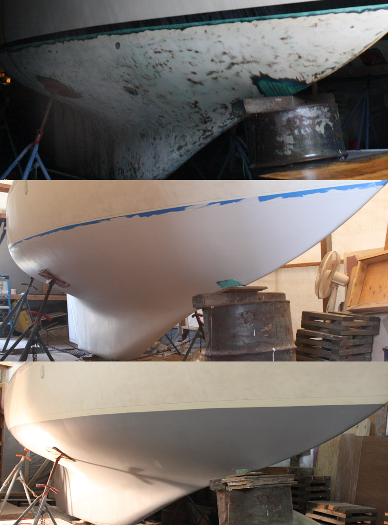
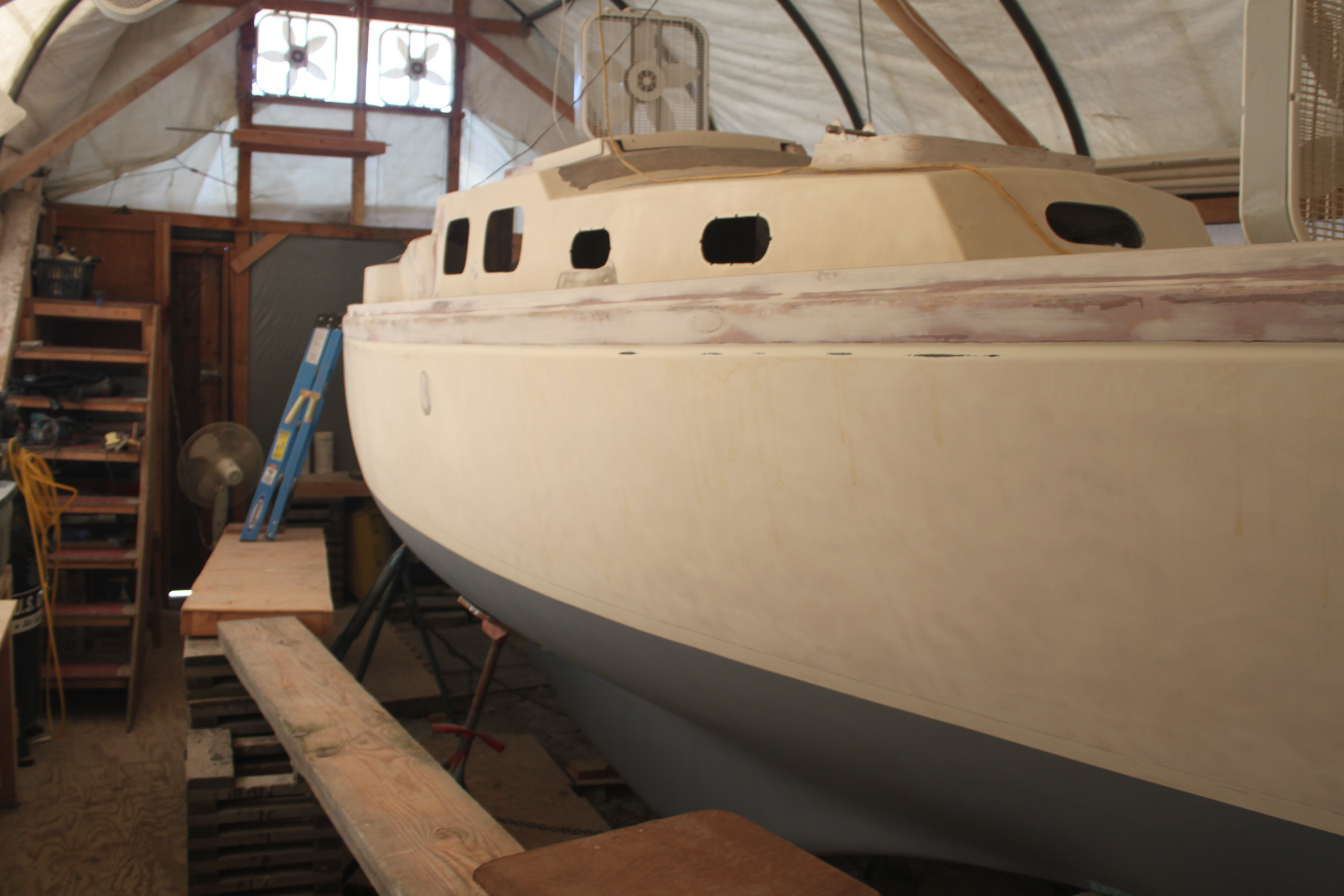
Four (4) coats of Interlux Barrier Kote have been applied to the bottom. As directed, colors alternated white and grey, so as to insure the bottom was well coated. Seeing a solid color on the bottom felt invigorating, and was the culmination of a lot of bottom work. To get to this point, work completed included: filling old through-hull holes, grinding out of a line of waterline pit marks, fairing of all through-hull and waterline pit marks and of course, a lot of sanding. One final coat of Barrier Kote should be applied just before bottom paint goes on, as directed by Interlux. And, since bottom paint will be applied just before the boat goes in the water, this grey color will be around for a little while.
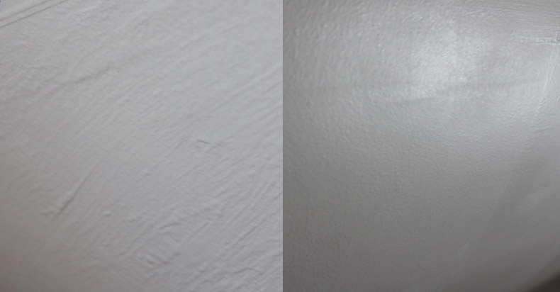
This was my first time applying Barrier Kote, and in fact, the first ‘paint’ that has been applied to the boat. As such, this was a learning opportunity for me. When applying the first coat, I mixed up an entire gallon of Barrier Kote and thought this may have been more paint than was needed to coat the entire bottom. I was concerned that there would be wasted paint, since once the catalyst was applied, the paint needed to be applied. In trying to use all the available paint, I began to roll on the paint too thickly at the bow and this ended up making a lot of ridges in the paint (as you can see in the image on the left). As I continued to paint from the bow, it became more clear that one (1) gallon was just enough to cover the entire bottom once, so there wasn’t the need to apply the paint so thickly. After this layer of paint dried, I decided to sand the ridges out of the paint, then paint on the second coat. The result was a much smoother painted surface, as shown in the image on the right.
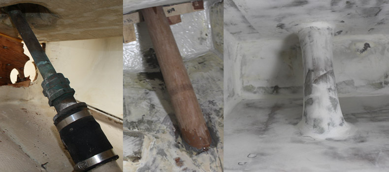
Before being able to hang the rudder, I completed a major modification of the rudder tube design. I decided to remove the original rudder tube (shown in the far left of the image) that employed a stuffing box. In it’s place, I installed a full length, 3″ Garolite tube that runs from the hull to the underside of the tiller head base. The tube and tiller head base were heavily installed with fiberglass. In addition to the strength gains, by doing away with the stuffing box, the rudder tube is completely maintenance free, with no possibility of leaks or a complete failure.
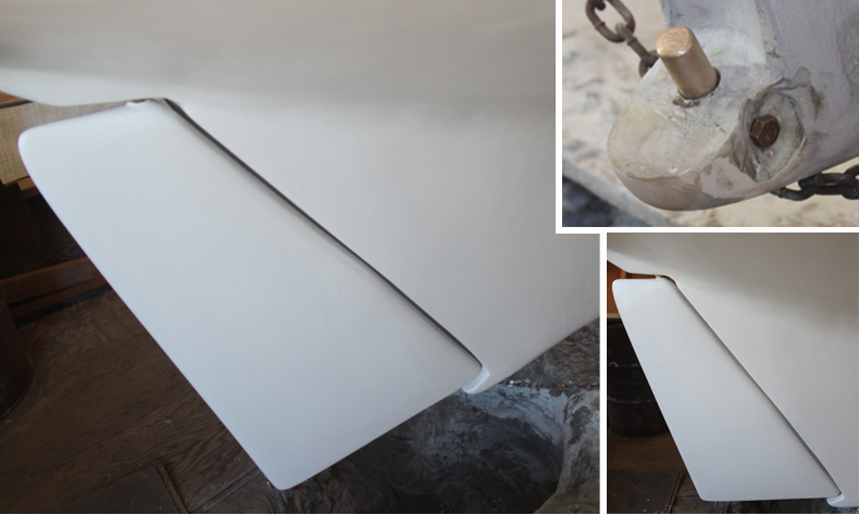
The rudder has been hung and a brand new, custom fit bronze pintle and fastener have been installed. Hanging the rudder was required in order to apply Barrier Kote. Bristol 27s have an interestingly simple rudder pintle set-up. The pintle enters the rudder through a hole in the bottom of the keel and is held in place by a fastener that is fiberglassed into the keel (see image in the top right). The fastener that secures the pintle is actually fiberglassed and in place and the rudder must be in place before the the pintle and fastener can be glassed. And since the bottom couldn’t have Barrier Kote applied until all fiberglass and fairing was complete the rudder was hung.
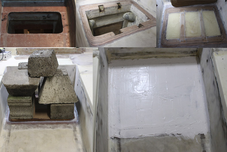
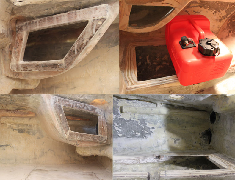
A cockpit sole hatch was part of the original cockpit design related to the use of an inboard diesel engine. This hatch allowed access to the engine’s waterlift muffler and below cockpit locker. The hatch was ready to be installed after cockpit construction was finished in 2012 (top left of the image). Now, in 2013, with the inboard diesel no longer part of the boat’s design, I decided to remove the hatch from the cockpit design. Access to the below cockpit locker will be via below decks, for reasons which I’ll describe in the ‘Interior’ images below. The image above shows the steps that were taken to fill this cockpit sole hatch opening. First, the old opening was ground to create a scarf joint (top middle image). Then, supports and a filler piece were glassed in place to fill the opening enough so pour foam could be added to fill the gap. Once the foam was shaped, a final top wooden piece was thickened onto the supports and above the foam, with the help of weights to push it firmly down (bottom left image). Finally, the wood piece was glassed in placed, then faired (bottom right image). More sanding and fairing is to come, but in general, this repair is complete.
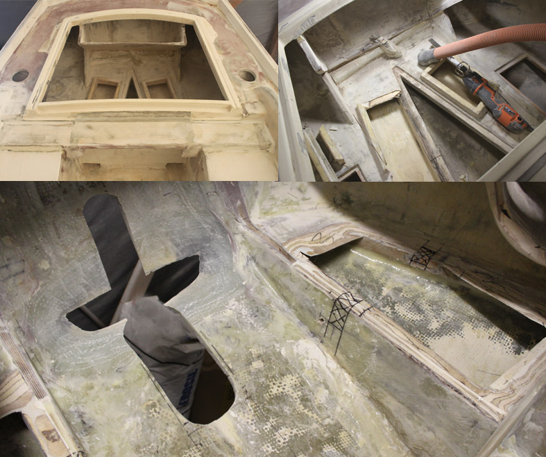
The lazarette was ready for paint after construction in 2012 (top left image). But after I made the decision to add an outboard motor in a well into the lazarette, it became necessary to demolish most of this completed work to accommodate the new motor. This image compilation shows the lazarette as it was, then demolition in progress, and finally the lazarette after it was fully demolished and ready for new construction. This image also shows how the traveler was removed due to the new motor well design. In it’s place, I’ll return the mainsheet block and tackle system used by many Bristol 27’s and Pearson Tritons.
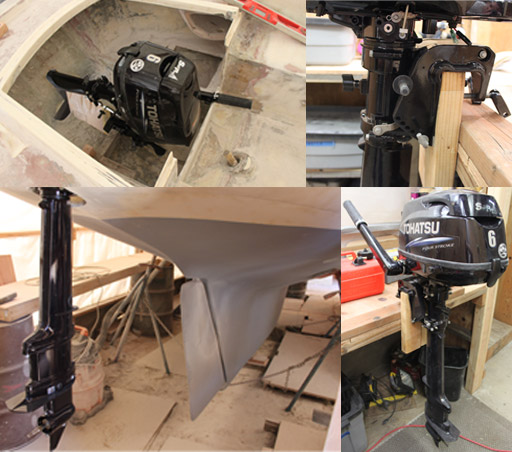
I decided to add an outboard motor in a well into the lazarette. This decision was a difficult one and choosing this route meant a series of cascading design changes around the boat. I’ve done a bit of writing about why this decision was made, and will post detailed information in the future. For now, I’ll use this image to succinctly show the new outboard motor. The motor in the image is a 6 hp Tohatsu Sail Pro. It has an extra long shaft, which allows it to reach well below the waterline, insuring the prop won’t cavitate when the boat pitches swells (bottom left image). It’s also small enough that it can be tilted up and out of the water when not in use and be fully contained in size the lazarette, after I shorten the tiller handle (top left image). A key design factor for installing the motor is it’s motor mount, which is shown in the top right image.
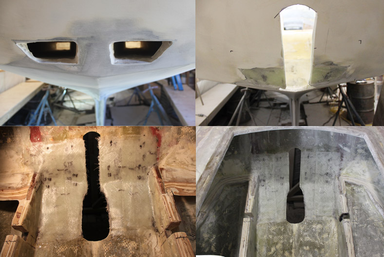
This image shows the new motor well cut-out that allows the motor to tilt up and down; in, and out of the water. 18 layers of 1708 biaxial fiberglass were added to fill the old cockpit drain channel holes (the original channel holes are shown in the top left image, with the channel holes filled shown in the top right image). I still need to do some fine tuning of this hole as construction in the lazarette continues, but the general idea can be clearly seen.
The port and starboard dorades that were built into the lazarette have been demolished to allow a better location for storing the fuel cans. The cans are needed to power the gasoline outboard motor. Originally, the dorades were meant to ventilate the inboard motor, but took up too much space with the new lazarette design. The vents will still be used to ventilate the interior of the boat, but the dorades will be redesigned to take-up less space in the lazarette.
Interior
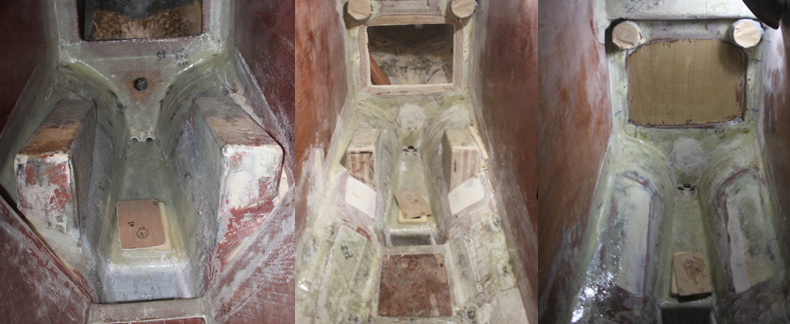
This image shows the inboard motor mounts that have now been completely removed from the boat. Their completed construction is shown in the far left, the partial demolition is shown in the middle image, and the final state of the mounts is shown in the right image. I had considered keeping the mounts in the ‘partial demolition’ state and using them as a base for a shelf in the new locker design. However, I decided against this, because they were quite heavy and took-up more space than I would have preferred. Plus, it’s probably easier to install a whole new piece for the new shelf design, rather than try to work with a part that wasn’t specifically designed for this purpose.
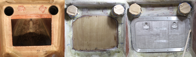
Access to the below cockpit locker is now through the old engine compartment. By moving this hatch below decks, it makes the cockpit sole smooth (no hatch protruding from the sole) and greatly improves access to the below cockpit locker (it was never easy to access the below cockpit locker by crawling, head first through the cockpit sole). Another benefit of moving this hatch is that it removes a hole on the outside of the boat (no matter how good the hatch, a hole is still a hole in the boat). The final benefit of installing this hatch below decks is that now, the below cockpit locker has a gasketed, purpose built hatch that allows this locker to be completely sealed off from the entire boat, which adds a water-tight locker for safety.
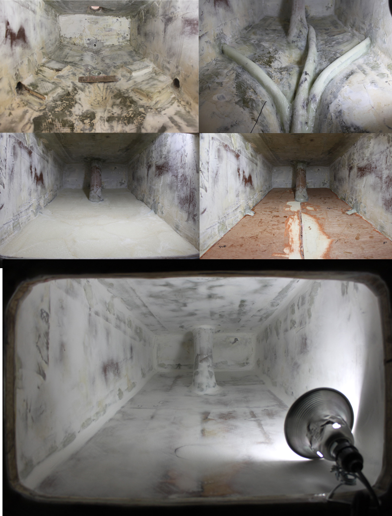
The below cockpit locker construction had been completed in 2012, but was redesigned in 2013 to be a fully water-tight locker. This option was opened up with the removal of the inboard motor, because with an inboard, it was necessary to pass the exhaust hose through this locker and out the transom, meaning the locker couldn’t have been water-tight. Without the exhaust line running through this locker I was able to add another water-tight locker to the boat. To achieve this water-tight goal, I also modified the rudder tube design (as mentioned above) and demolished the old deck locker drains. The deck locker drains originally just drained into the below cockpit locker, eventually finding their way into the bilge. With a new goal of a complete water-tight locker, the old drains were removed and replaced with full length PVC drain pipes (top right image) which can be closed off with a PVC valve in the old engine compartment locker. Having full length drains that can be fully closed also means that any gas stored in these lockers won’t allow fumes into the boat’s bilge. Once the new rudder tube and drains were installed, I then decided to ‘level’ the entire below cockpit locker sole, which would allow sliding items to the back of this locker, for easier stowage (as opposed to lifting them over the drain pipes). The new locker sole was created by pouring foam over the drain lines (middle left image), then adding two pieces of 1/4″ luan over the foam for impact strength (middle right image), then finally glassing and fairing the luan (bottom image). At this point, the below cockpit locker is fully ready for paint.
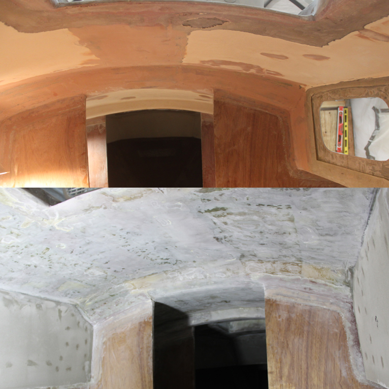
I decided to demolish the previously installed headliner in the saloon, head area and v-berth. The decision didn’t come easy, because it meant a lot of additional work, but by removing the old headliner, it would allow me to install ~3.8 cm (1.5″) of Airex C70.75 foam to the underside of the cabin-top. This would give me an insulation R-value of ~6.525 over the entire cabin top. My hope is that this increased insulation makes the boat a lot more livable, by reducing condensation and averaging interior temperatures.
This image shows the new forward portlight I decided to add. I felt a forward portlight would bring in some nice light, and also give more well rounded visibility when inside the cabin, which will be especially when going down below while underway. I was a little concerned that the forward portlight might damage the look of the boat, but after drawing the window on the boat and taking a look at it over a week or so, I felt it should look fine.
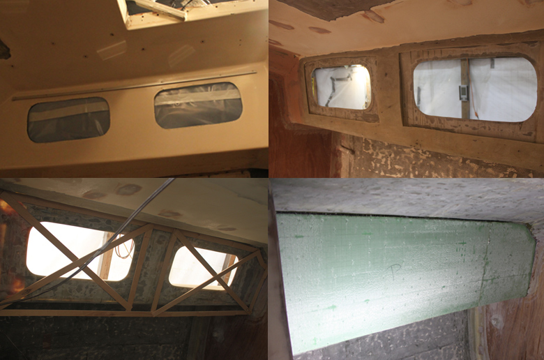
This image shows the saloon headliner and portlight progress. The top left image shows the portlight holes as they were when I first purchased the boat. The top right image shows the portlight design I had planned to use, when I was just going to add a flange to increase the thickness of the portlight pane and use the original portlight frames. After more thought and discussion, it became clear that if I used the existing portlight frames, they had a weak point, which was a 0.635 cm (.25″) bedding surface onto which the portlight pane could mount and sealant could be applied. This would mean that portlights would be prone to leaks. To remedy this, I decided to create a new interior flange for the portlights to rest on made of structural, fiberglassed foam. The portlights will be installed flush to the cabin side onto this new flange. They will be secured to the cabin with t-nuts and 1/4″ fasteners. It’s a little hard to explain the exact plan in a image comment, so look for a full write-up of this new portlight design in the months to come. However, for now, the two bottom images show the headliner removed and the new layers of foam being added to begin the build-up for the portlight flanges.
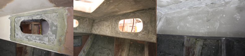
This image shows the starboard v-berth portlight’s progression. From the left, it shows the original demolition I did, then the headliner fully removed, and the far right image shows one (1) layer of H80 foam thickened into the cabin side. The v-berth portlights will have the same portlight design as the saloon portlights.
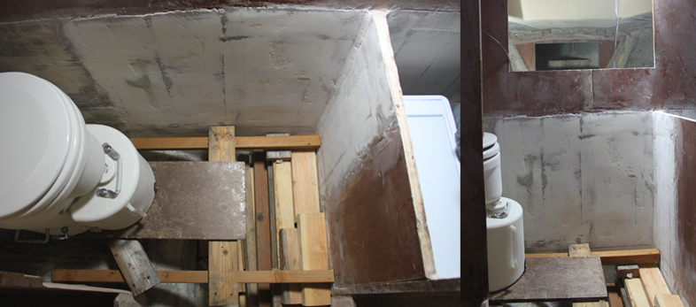
The last News post showed how the old head area had been demolished in order to make room for an easier to use head. This image shows some planning work for how the new head will be placed, and how it will stick out just beyond the existing bulkhead installation. I probably won’t get to constructing this newhead area for some time, but the basic idea for the head’s placement is shown here. The image on the left also shows the new 12v icebox’s storage location, which I’ll describe in more detail below.
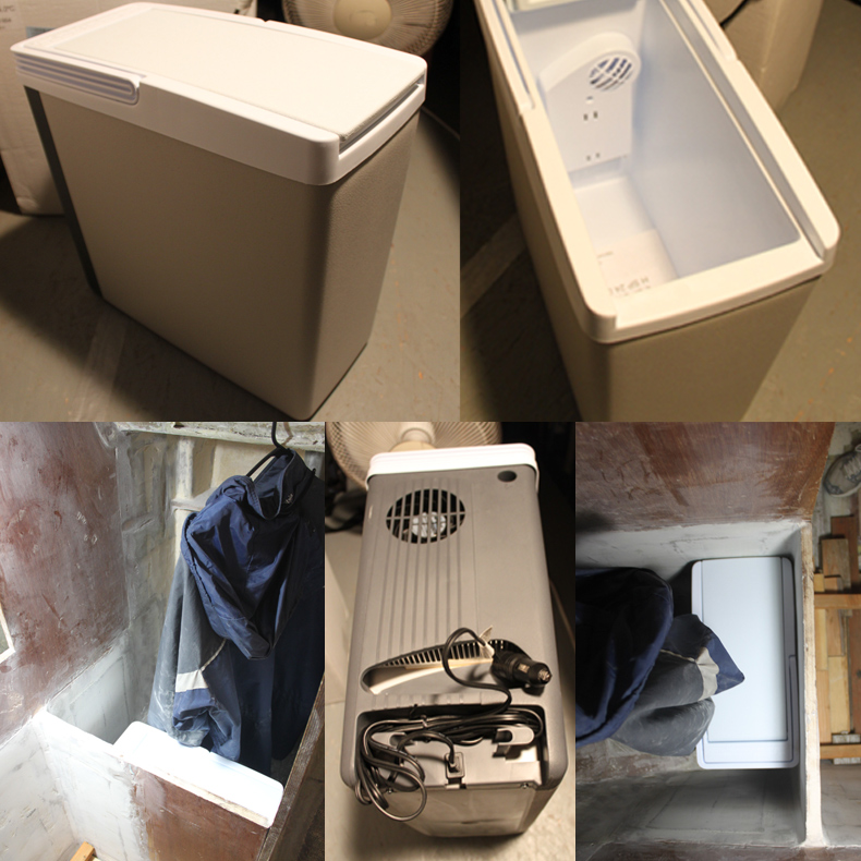
The last News post showed how I had demolished the old icebox, in favor of a removable, 12V icebox. This image shows the new 12v icebox that will be used and it’s placement in the bottom of the hanging locker. It’s not a large icebox, but it should be enough to stow the basics.

A minor change, but one that still took most of a day was removing a large backing plate that was installed on the underside of the deck in the chain locker. Originally, this backing plate was meant to support a manual windlass, but I have since done away with the idea of using a windlass and wanted to reduce weight in the bows as much as possible, so this backing plate was removed.
General Project Status Update
As is probably clear from the images above, there have been a few more design modifications that meant yet more demolition of already completed projects. I do believe that these design decisions will make the boat more livable in the end, even if it does mean more money, time and effort in the short term. I’ll just continue to make slow and steady progress, and before long, things will really start to take shape.
Another thing to note is that Mark Williams is no longer working on the project with me as of late July. The decision was multi-faceted, but related to project funding and giving Mark the chance to take on other business opportunities for his newly started marine repair business ‘Night Owl Marine’. Other factors were my desire to complete the boat project with my own hands and being more content with the project moving at a speed more inline with the reality of completing a project such as this.
The good news is that I’m not entirely without help, as my partner, Megan, started coming to the boat shed about one day per weekend. She’ll also be taking on the canvaswork projects (e.g. dodger, bimini, cushions, sails, etc.). It’s been great fun to work with her on the project. I’ve really appreciated having her involved and to have another person understand the process I’m working through.
Finally, it’s probably obvious that updates to my site have slowed in recent months. This is mainly because there just aren’t enough hours in the day to complete my full-time job, boat construction and keep-up with the site. I’ll continue to do my best to update the site whenever possible, and once boat-construction slows down, I have a massive (700+ page) backlog of information to post on the site.
Do feel free to leave your comments or e-mail me with any questions you have. Thank you for following along.
Comment Form