The Cost of Cruising
This post has been a long time coming and there’s much to say. If you don’t have much time, here’s the tl;dr (too long; didn’t read):
Learned that money is an inescapable part of life; developed strategy to interweave this new fact into the boatbuilding and cruising dream
If you do have time, this post will better explain what’s been going on with this project since the start of 2014.
A Cruising Budget
In early 2014, boatbuilding was moving at a good pace and cruising seemed just around the corner. To prepare for the sailing trip, a yearly cruising budget was created. Here’s an image of the yearly cruising budget spreadsheet:
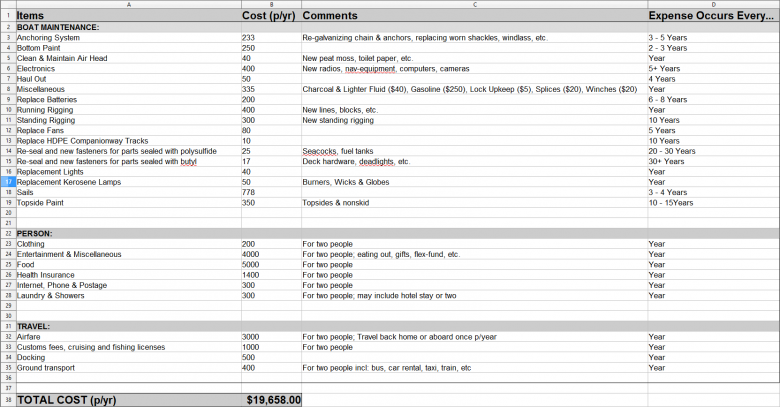
This image shows the estimated yearly budget for sailboat cruising.
The biggest take away from these calculations is that cruising should cost ~$20,000 per year. Here’s a few other notes:
- All costs are estimates, and surely this cost will vary, but this number is the best reference point based on existing information. $20,000 per year is living fairly “bare bones”. For example, instead of docking the boat in a marina, the boat will be anchored out 99% of the time. Another example is that many meals will be cooked onboard.
- Boat Maintenance is a pretty good estimate, since it was sourced via extensive research. Maintenance costs per year is calculated by taking the lowest number of years it might take to replace this item, then dividing that number of years by the total cost of the item being maintained. For example, if new batteries cost ~$1,200, then it’s required to save $200 per year over six years (the expected life of the battery) to cover the battery replacement cost.
- Person & Travel costs concatenated from various research documents.
How to Pay for Cruising?
Up until early 2014 the plan to pay for cruising was: save up enough funds, then go sailing. However, after calculating yearly cruising costs and comparing it to savings, it was clear that living off savings would allow only a finite number of years of cruising. And since one original goal of this project is long term cruising, a financial change in course was necessary and I worked to change my outlook
While initially hesitant to accept money as a factor in this voyage, I now better understand and acknowledge money’s inescapable role in modern life. Paying for big, long term goals is something every dreamer must address. There’s no one-size-fits-all approach for funding a dream, but when developing a plan to address the $20,000 yearly cruising costs, I took into consideration things like my: relationships, age, geographic location, personality, skills, education, societal trends, life philosophy and more.
After taking these factors into account, here’s some funding ideas that were decided against:
Crowdfunding – A newer approach to raising funds, where online donors pledge a flat or recurring dollar amount towards a project needing funding. While this approach can work for some, I wouldn’t feel right asking others to pay for my dream.
Return on Investment(s) – Generating $20,000 per year from investment without drawing down the capital requires a large lump sum. For example, an investment returning 4% per year requires an initial sum of $500,000 to return $20,000 per year. Since finding an investment that guarantees a 4% return per year is difficult and I don’t have access to the initial capital, living off of investment returns wasn’t a feasible funding route.
Start a Business – While I’d like to found a business eventually, the reality is that a business requires 100% focus and dedication. Since my attention was split over too many projects and responsibilities, layering on a business launch seemed tenuous. In the meantime, I’ll continue to track trends and ideas, then deploy an idea that’s a good fit.
Second Job – Was already working 8 – 5+, while often spending evenings at the boat, so there just wasn’t much time to add in a second job. Plus, I had already decided against trying to live off of savings, and would prefer to have an investment with recurring cash flow.
And finally, here’s the idea that my partner and I decided to move forward on:
Real Estate – Real estate is a time tested investment method. Specifically, research indicated that multi-unit property might be the only method to generate the required $20,000 yearly cruising funds. There are many pros and cons to this approach, more specifics on exactly how the investment returns and much more. However, I won’t go into all those details here and will instead try to show how this project has affected the boatbuilding portion of my cruising dream.
118-year-old Duplex
The multi-unit property search started in February, 2014. After lots of searching and effort, by November 2014, we had closed on a duplex built in 1898. On the surface, the property seemed old and in need of a few repairs, but the inspection didn’t uncover any major issues and it seemed ready for rent. However, on the very first night and after moving all day, we went to take a shower in one of the units and there wasn’t any hot water. I thought “Not a problem, I’ll just complete this repair and we’ll be back in business”. Unfortunately, what started as a minor repair turned into the discovery of a spider web of other major issues and a seemingly “ready to go” property turned into a total gut and remodel project.
Here’s a list of the key repairs that needed to be completed in order to make the house safe for occupancy:
- Many floor joists ends didn’t have any end bearing, meaning they were offering little support to the floors above.
- Many floor joists had large holes cut through them, meaning their structural integrity was greatly compromised.
- 2nd floor, east bedroom’s 2×6 floor joists spanned 15′, which is an overspan of ~6′.
- Interior walls built with planks only, no studs.
- Sewer drain leaking at the clean-out fitting that passes through the foundation slab.
- Gutters draining against the foundation.
- At least ten (10) leaks in the roof, with one leak actually being a 8″ circular hole in the roof that was hidden under an eave.
- Upstairs tub was leaking into a hidden area between walls, creating rot and potential for mold.
- Sinks leaking into the cabinets below causing rot.
- Animals had been living between the 1st and 2nd floors. There were smelly nests in every nook and cranny and a dead squirrel was found inside a wall. Besides being unsanitary, the animal infestation was also unsafe, because the animals had chewed through the insulation of numerous electrical wires, creating a dangerous fire hazard.
- No fire blocking between floors.
It would seem that these issues should have come-up during the pre-purchase house inspection, but most of the problems were either hidden behind drywall, not visible under all conditions (e.g. roof leaks, sewer leak, gutter drainage) or didn’t exist until there was full-time occupancy (e.g. leaking sinks wasn’t obvious initially, but with full time use the issue became obvious). And so, with a grin on my face, work began in earnest.
Below are images of projects, listed in basic chronological order (starting in December, 2014 up until March, 2016):
Basement
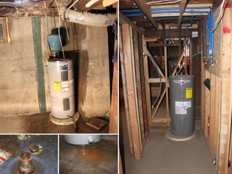
Images on the left showing the water heater repair that started the entire remodel project. The two bottom left images show how corroded the water heater was. The image on the right shows the one of two water heaters installed as of March, 2016.
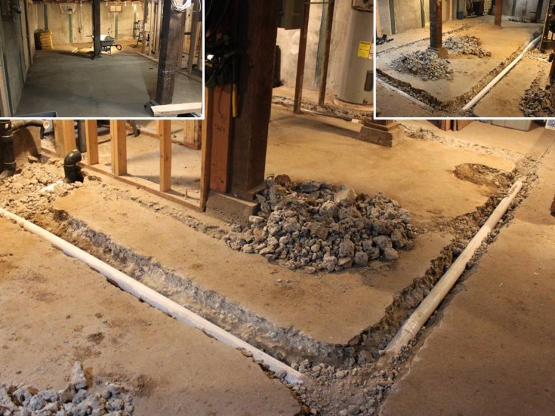
The property tested positive for higher that allowed radon levels. To resolve this, a passive radon collection system was installed. The system routes under all key sections of the foundation slab. All pipes are connected in loops, so that if one side were to get clogged, air would still flow. The system is passive, meaning there’s no need for a fan to constantly. Instead of a fan, there’s an exhaust point that vents to the exterior. A clean-out was also added and can be seen as the black ABS sticking out just under the top left image. The main image and top right image shown the radon piping that loops under the foundation. The top left image shows the radon system after it’s been concreted over.
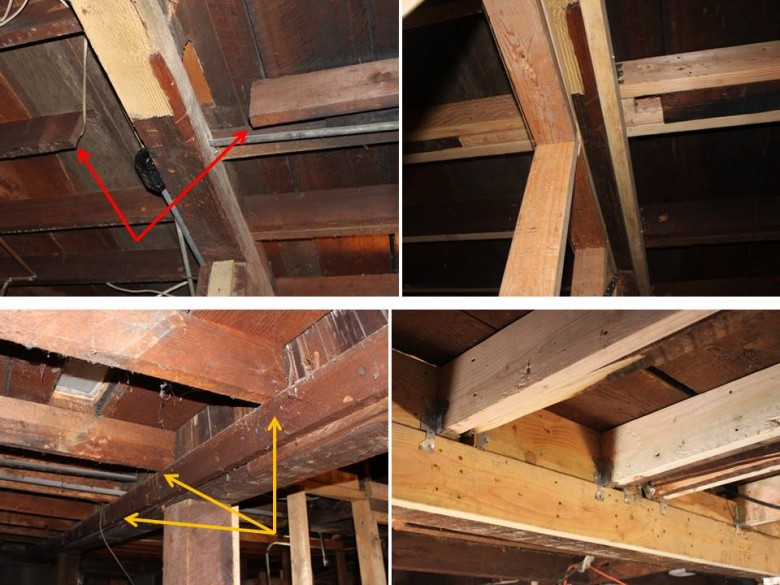
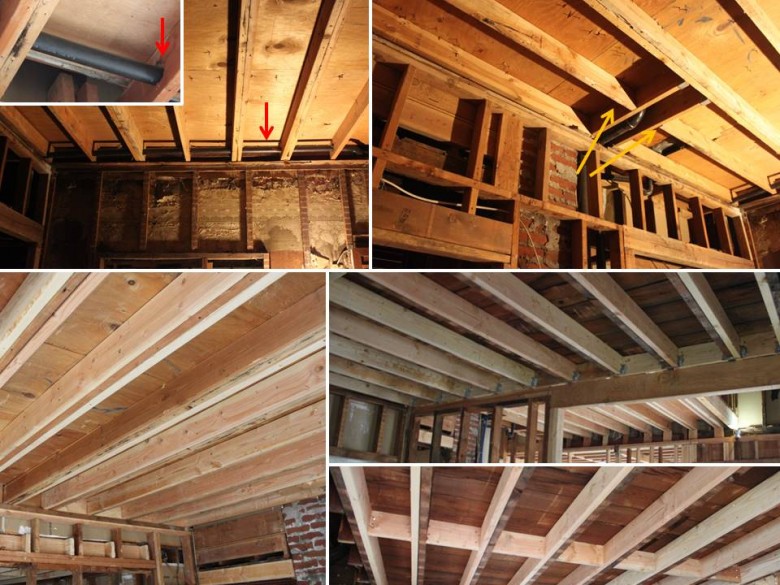
Many of the first floor joists were unsafe and this image shows a couple examples of the issues. The top left image is an example of one of the joists that was cut (see red arrows), while the top right image shows the same joist repaired. The bottom left image shows joists that supported the living room of one of the units. The orange arrows show the 2×4 that was meant to provide bearing for these joists, but held on by just a few nails – very unsafe! The bottom right image shows the repair made, where a new bearing board was installed and well secured to the beams.
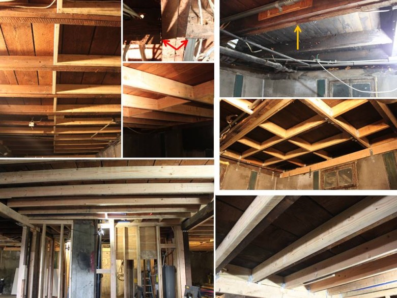
More images of the first floor joints. The red arrows show an example of how numerous joists were toe nailed without joist hangers. The orange arrow shows a 2×6 joist that’s supporting a two story exterior wall. There are actually two joists there, but one had been cut off so it had no bearing on it’s west side. The image below the image with the orange arrow shows the final arrangement of this area, where the key joist has been turned into a beam by two new joists being added and all four joists bolted together to create a single beam. The other images show various repairs on the 1st floor joists. All joists were doubled, had blocking added, plus many A35 framing angles. After completing this work, the first floor feels 100% stronger and much less bouncy.
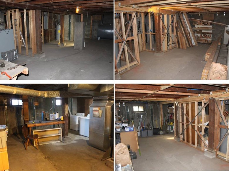
This image shows the east portion of the basement, with before images on the left and after images on the right. The basement was originally shared, with each unit having access to the entire basement. There was also an oil powered furnace in the basement that heated just part of one of the units. This system (incl. ducting, oil tank and furnace), took up too much space in the basement, had an odd heating arrangement and was old and oil powered, so it was removed. The framing and earthquake improvements are clear from the images on the right side.
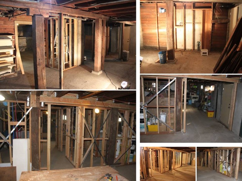
This image shows the east portion of the basement. Before images are at the top, after images on the bottom. As can be seen, the basement was both opened up, while also better partitioned to allow for each unit to have it’s own space in the basement.
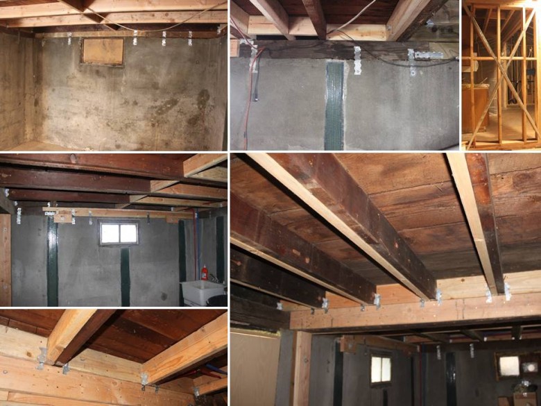
With all the framing exposed and easily accessible, now seemed a good time to install seismic strengthening to reduce potential earthquake damage. Key upgrades included: strapping the mud plate to the foundation, installing A35 framing angles on every joist and installing numerous sheer walls.
Exterior Drainage

Progression of installing a new drywell and connected drain pipes. A drywell was added to resolve improper gutter drainage and to add a drain route for a sunken window well for an egress window, a drywell was added to the north side of the property. An extra long drain pipe was added along this entire side of the house in the hopes that it would capture water from the neighbor house’s main gutter outlet which pours out nearby the wall shown in these images.
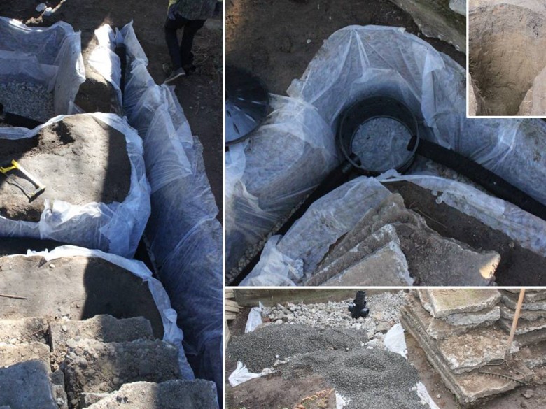
More images of the drywall being installed. The egress window well can be seen in the top left of this image. After the drywell was in the ground, the basement was much dryer. Digging holes was fun and there’s more drywells to install, but exterior work was postponed after this drywall was installed to focus back on the interior of the house.
First Floor
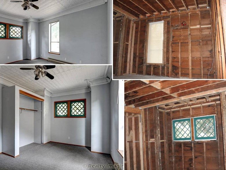
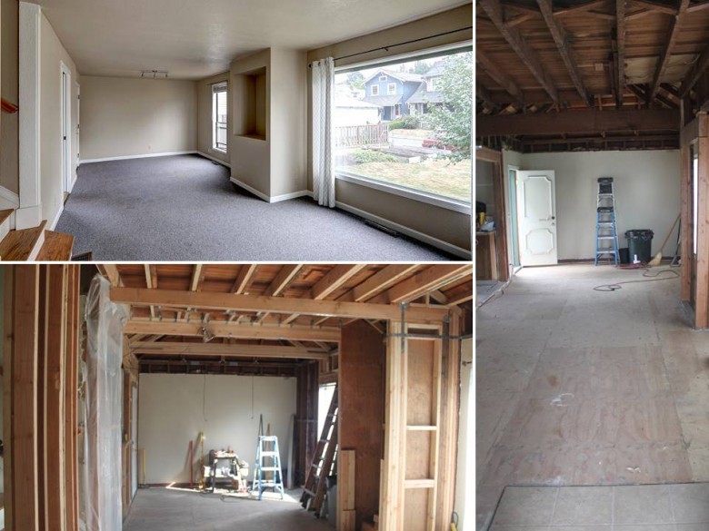
The next three images show the 1-bedroom unit of the duplex. This unit’s layout was odd, since accessing the kitchen and bathroom required walking through the living room and bedroom. The re-design will make the flow much better, so that the living room and kitchen are opened up and connected to one another. This particular image shows the bedroom as it initially existed (left two images) plus the new framing work that was done (right two images).
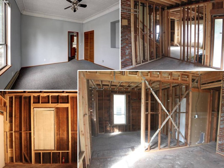
The living room as it existed initially. The top left image shows the living room as it existed initially, viewed from unit’s front door. The bottom right image is also from the unit’s front door, but this time after the framing had been done to open up the two rooms. The top right images shows the new demising wall between units (more info on this below). The bottom left image shows the south exterior wall that was framed during the remodel. Previously, this southern wall was only made of planks and no studs. The window of this south wall was also framed out for an increase in size.
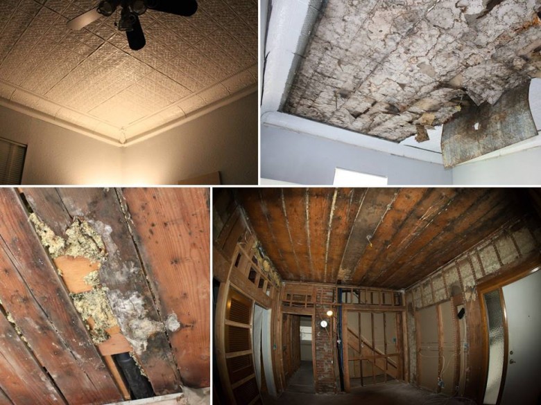
This unit had antique tin ceilings. We were hesitant to remove the tin, since a lot of people seemed to like the look. However, in an effort to add sound insulation, the existing ceiling had to be removed to allow new drywall and sound channels to be added. It’s a good thing the ceiling was removed, because as is visible in these images, the space between floors had mold, animal nests and long term water damage. There were also structural issues that were discovered (more on that in the next image).
This image shows joists that were structurally unsound, then repaired. The red arrows show a drain pipe that was drilled through 2″ holes through the 2×6 joists supporting the upstairs bathroom, which is a code violation, since 2×6 joists may have a 1.5″ bored hole maximum. The orange arrows are another example of joists being toe nailed instead of attached with joist hangers. The bottom images show how all the second floor joists were doubled (and in some places tripled) plus A35 framing angles were added to hold all the joists in place in case of an earthquake. Now, the second floor is much safer and structurally sound.
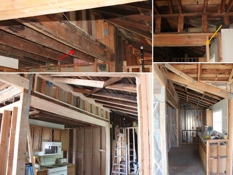
Removing drywall to add improved sound insulation in the 2-bedroom unit also uncovered major structural issues. The red arrow shows a sagging 2×6 joist in the 2-bedroom kitchen that’s supporting an exterior wall, and the image below the red arrowed image shows the new beam that was added to reinforce the floor above. The orange arrow shows a beam that didn’t have any bearing and was barely staying aloft at all. This beam was replaced when the ceiling was changed from flat to vaulted.
The 2-bedroom living room is shown in this image. The original room is shown in the top left, and the other two images shown the framing work completed as of March 2016.

The top four images show perhaps one of the most shocking structural issues discovered. The red arrows show a 2×12 beam that was supporting the roof and second floor. It’s amazing that this part of house hadn’t collapsed, since this beam was attached with two toe nails and didn’t have any bearing on one end. This beam was removed and replaced by a 4×12 glue laminated beam. The new beam has great bearing and is held in place by straps, A35 framing angles and brackets. The bottom three images show another structural issue and it’s resolution. The orange arrow shows another scary situation, where a 2×4 was laid on it’s side and used as a “beam” to support an exterior upper wall. This 2×4 was removed and replaced with another 4×12 glue laminated beam that also received lots of hardware to hold it in place in case of an earthquake.
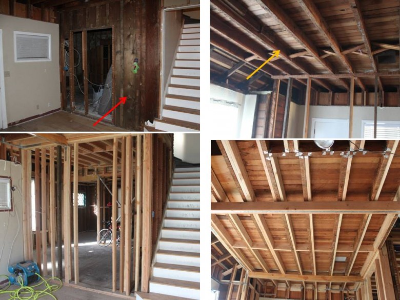
The top-left image shows the original demising wall made only of planks. The bottom-left image shows how this planked demising was demolished, then replaced with a staggered stud wall (staggered studs will help reduce sound passing between units). The top right image shows has an orange arrow that points to one of the over-spanned joists that support the second floor. These joists were all doubled and beams were added to remove the overspan issues.
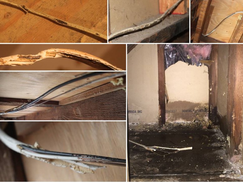
For some time, the home sat empty and wasn’t well kept. Due to this, animals (likely squirrels) had gotten into the house over time and built their own homes. As part of their homemaking exercise, they chewed through many electrical wires. This image shows some of the wires they ate through. Besides animals chewing through wires, there were many leaks in the roof. The bottom right image shows one of these leaks, which had been leaking right into an exposed wire.
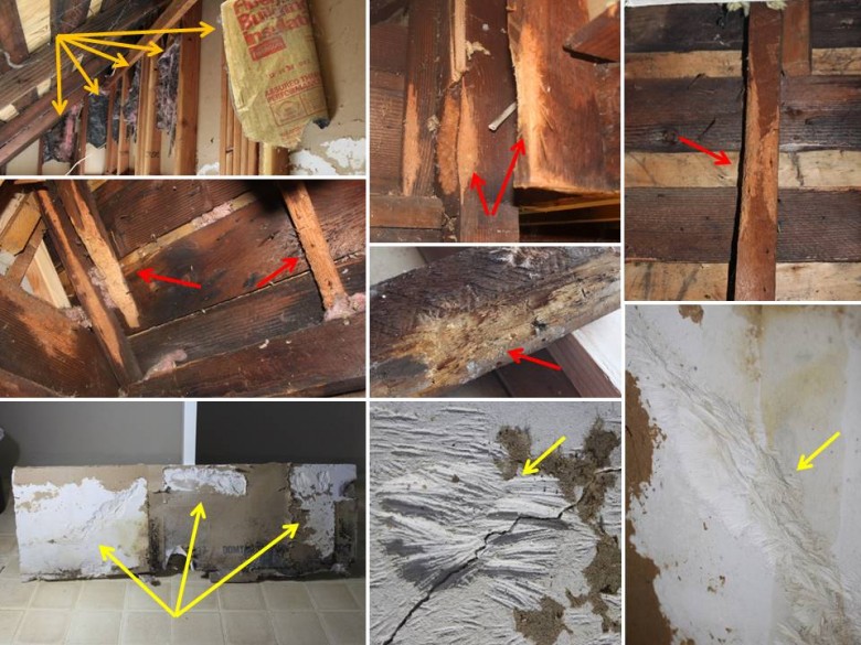
Besides chewing through electrical wires, the animals also chewed through wood (see red arrows), ate away insulation (orange arrows) and even chewed through the drywall (yellow arrows). In fact, in one wall, the animals had chewed all the way through the drywall and likely had access to the interior of the house as well (not just the space between floors).
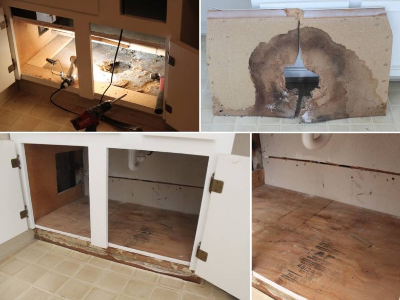
The upstairs bathroom sink was leaking and caused major rot, which is shown in the top two images. The rot was actually hidden below some plywood that was installed on top of the rot. The bottom two images show the rot that was all removed and and repaired.
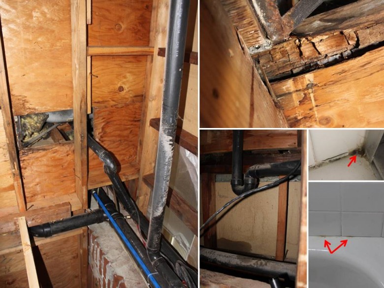
The upstairs bathtub was leaking into the wall and into a hidden space between two walls. The rot and leak is noticeable in the three left-most images. The bottom right two images have red arrows which show where I believe the water was seeping in behind the tile. Once behind the tile, it seeped down to one corner of the tub where it rotted the floor and created mold between walls. The tub has since been re-caulked and the rot was fixed.
Boat Project
Besides the duplex project, I’d also like to share the boatbuilding work completed between September 2013 to June 2014. During this time frame, construction of the new motor well that holds a 6 hp Tohatsu sail pro long shaft motor was 100% completed. In addition, deadlight frames and deck vent construction are also mostly complete. Once my attention is back on the boat project, the main focus is getting the exterior completed, then I’ll move inside to build the cabinetry.
Here’s some images of the work completed during this 9/2013 – 6/2014 time frame:
Motor Well
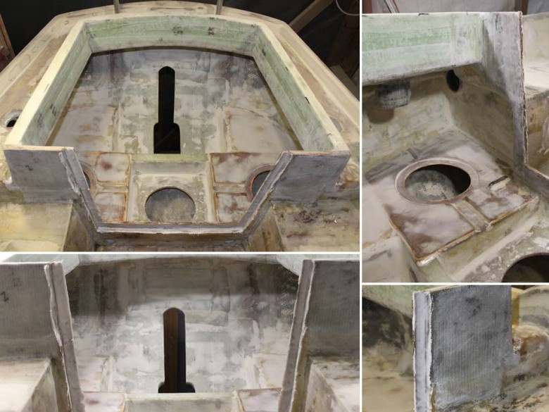
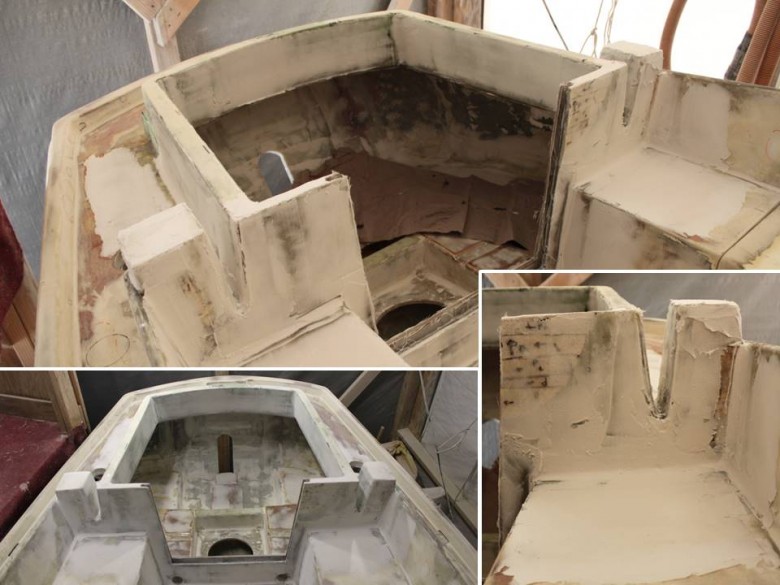
The Summer Construction News post from September, 2013 shows how the lazarette was demolished to make way for a new motor well design. The next 11 images show the construction of the motor well from demolition to final form. The exact design and construction specifics will eventually be covered in more detail, but for now, the following captions and images should provide a decent understanding.
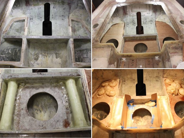
The top left image shows the motor mounting bracket (running athwartships). The motor mounting bracket is a critical and high stress part, so it was made of two 3/4″ pieces of marine plywood thickened together. Then, the plywood part was placed into the locker bulkheads, creating a dado joint. Once in place, the bracket was heavily fiberglassed to the hull and nearby members. The top right image shows the motor well locker tops being test installed. The bottom two images show the new cockpit drainage arrangement. The cockpit will now drain through these 2″ PVC tubes, into the motor well where it drains out of the boat. Once the PVC drain tubes were installed, foam was poured over them, plus into the aft-most areas of the lockers which wouldn’t be accessible in the final locker design (as shown in the bottom right image).
When titled up and out of the water, the 6 hp motor was too tall to fit under the existing lazarette lid. To resolve this, the lazarette lid flange was built up using 7 layers of closed cell foam. Each layer of foam was added individually by using thickened epoxy between each layer of foam. Once the foam pieces were installed, they were shaped and fiberglassed into place.
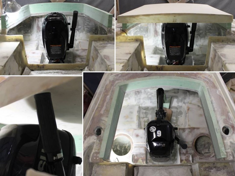
Image showing the outboard motor in the tilted up position. The bottom left image shows how the motor’s throttle handle just barely fits under the lazarette lid. The bottom right image is a good top view of the motor well arrangement plus the the locker tops and cockpit drains fiberglassed.
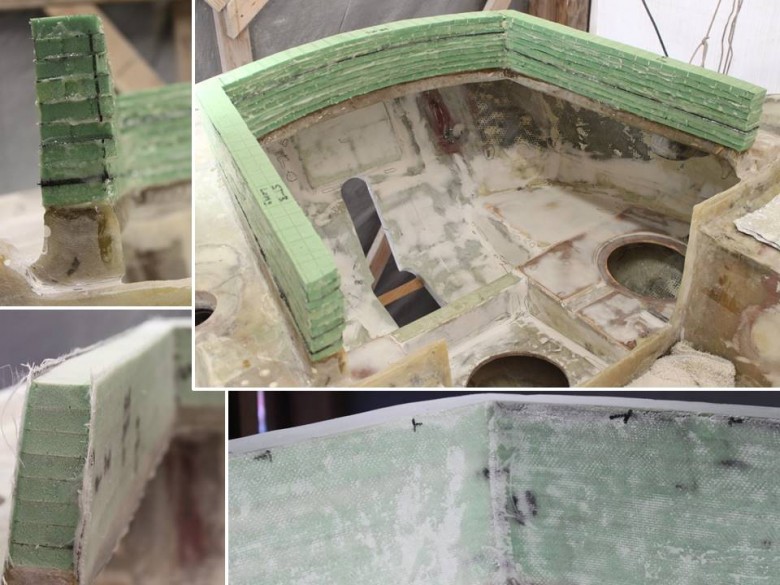
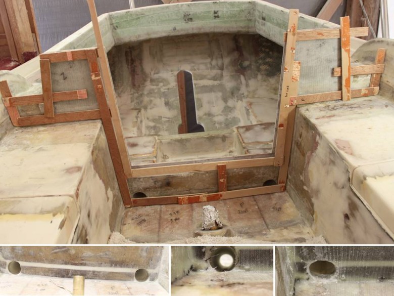
With the interior and lazarette lid flanges built, the next step was to build a door that gave access to the motor well. Not adding a door/hatch was considered, but tests showed that it would be much better to have clear and easy access to this space. This image shows the beginning of the creation of the flange that holds the door in place. The top left image shows the template for this aft part of the door flange, while the bottom two images show the actual plywood flange being installed. I used some older 1/4″ marine plywood that had warped in storage, which is why rope and zip ties were used to hold the flange in proper alignment for glassing. The top right image shows a “spacer” piece that was installed on top of the aft-flange piece. This space piece creates enough room between the aft- and forward-flange parts so that a door can be slid between the two flanges.
This image shows the fiberglassing of the aft-flange and spacer piece. The top right image shows the backside of this flange, plus a good shot of the interior of the motor well.
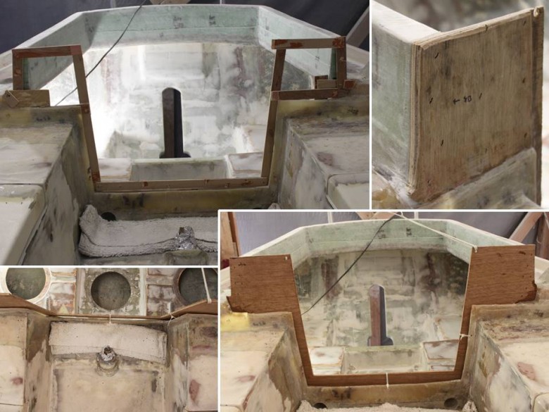
With the aft-flange and spacer piece fiberglassed, the forward-flange piece was templated, then installed. The large image shows this template, while the bottom images show the progression of the forward-flange installed, then fiberglassed. The bottom right two images show how the cockpit drains were fiberglassed and fine-tuned. It was important that these drains were completely flush with the cockpit sole so that no water would collect in this area.
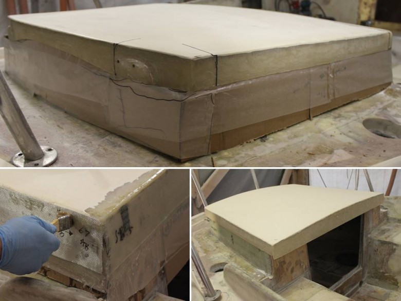
With the door flange complete, it was now possible to fit the lazarette lid. I found that the original lazarette lid was slightly too large due to the new lazarette lid flange which gets slight smaller as it gets taller Also, the sides of the original lazarette lid were a little too short and I was concerned water could splash up and through this slot, plus I thought the flange would less tall if the lazarette lid sides extended a bit further downward. So, I cut the front off of the lazarette lid, used the new lazarette lid flanges as a template by adding cardboard and wax paper, then glassed the new sides of the lazarette lid.
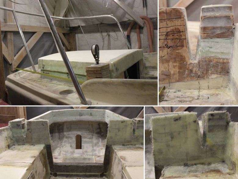
This image set shows the creation of the mainsheet block mounting platforms. The mainsheet blocks needed to be raised above the height of the motor well so the sheets would have freedom to move athwartships. Another wrinkle is that the self steering lines needed to pass between the new mainsheet block mounting platforms and new motor well lid flange
Fairing the new construction to seamlessly blend in with the rest of the boat.
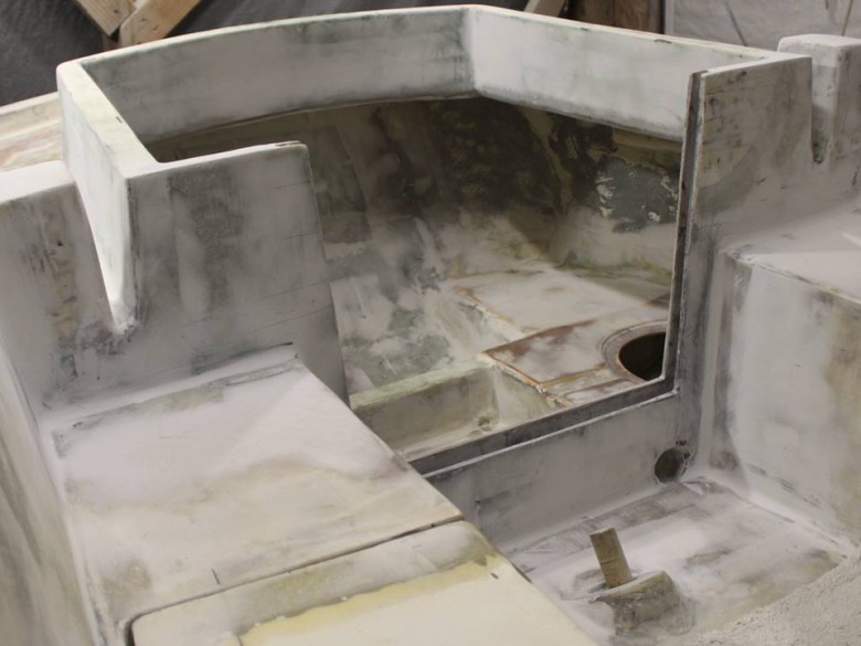
Larger image of the motor well construction completed and faired. This area is now ready for paint.
Fairing
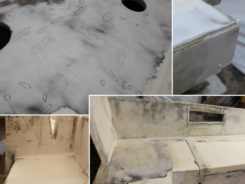
Image showing a few of the various fairing projects done during the September to June time frame. There’s much fairing to be done around the boat and this image is just a sample of that. Note that I have a habit of using permanent pen to make initial marks showing where fairing needs to be done. Usually, when sanding the fairing, these marks are hidden. However, looking at these images again I’m likely going to reduce the amount of permanent pen I use, because I wouldn’t want these pen marks showing through after the final paint job.
New Chainplates
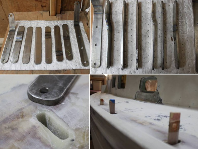
Titanium chainplates have been crafted. The top two images show the chainplates laid out. The bottom two images show the through deck penetrations being made to fit the chainplates. The exact placement of these penetrations is paramount, since the chainplates must line-up exactly in the center of the mast, otherwise the standing rigging will be unbalanced.
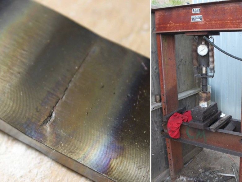
This titanium chainplate project has been wrought with troubles. I had the person who created the chainplates match the bends that existed in the original chainplates. Now, I think the bends that existed in the original chainplates were potentially due to damage and having kept the new chainplates straight would have been the right choice. To resolve this error, I tried to cold press the titanium back to flat (at the suggestion of a respected welder in my yard). Unfortunately, when performing this press, the titanium cracked (as shown in the left image). I’ll resolve these troubles eventually, but for now their resolution is pending.
Deadlights
The Summer Construction News post from September, 2013 shows the start of creating the flanges for the deadlights. Instead of using portlights (which open), the boat will use deadlights (which don’t open). The next 3 images show the construction of the flanges for the deadlights. Just like with the motor well, the exact design and construction specifics will be covered in more detail at a later time.
This images shows the deadlight flange ready for cut-out. The top left image shows the basic shape to be cut out of 3 layers of structural, closed cell phone. To make the cut, a router with a special long straight router bit was used. The router bit burned out after just a few minutes of use (shown in the bottom left image), so I had to buy another bit to make the other deadlight opening cuts. This was actually one of my very first times using a router and I was happy with the results.

Image in the top left showing the deadlight flanges before they were cut. Then the other 2 images show the deadlight flanges cut and ready for fiberglassing.
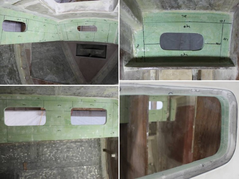
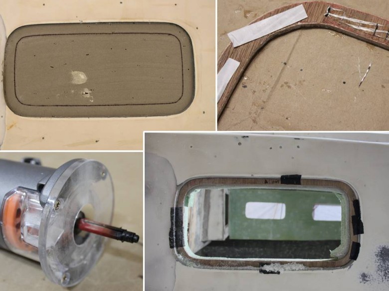
Interior images of the deadlight flanges. The markings on the green foam show where fiberglass will be installed. The bottom right image shows the deadlight flange from the outside looking in. The acrylic deadlight lens will sit on top of the gray foam and be flush with the cabin side, providing a clean and modern look.
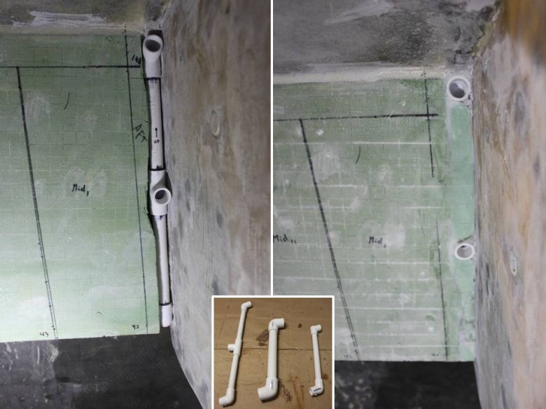
Wire runs were also built into the headliner as part of the deadlight flange construction. PVC was used for the wire runs and will allow wires to run from down low, up to instruments and lighting mounted on the headliner.
Deck Vents
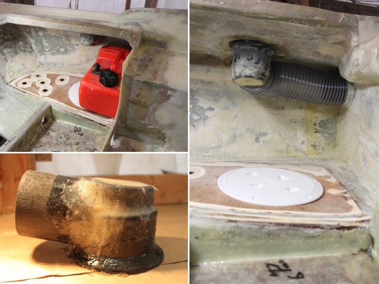
Ventilation was a critical design element for any boat and even more-so for boats with deadlights which don’t open. This image shows the stern deck vent construction. Originally, the stern vents were to ventilate the inboard motor. Now, with the inboard motor gone, this vent will serve as a general purpose cabin vent. This vent is arrangement is very much custom. The bottom left image shows how different ABS drain parts were combined, then epoxy and fiberglassed together to make a fitting that attaches just below a mushroom vent on deck. The right image shows how this custom vent piece was epoxied below deck, which allows air to pass to/from the on deck mushroom vents, through dust collection hose, and into the main cabin.
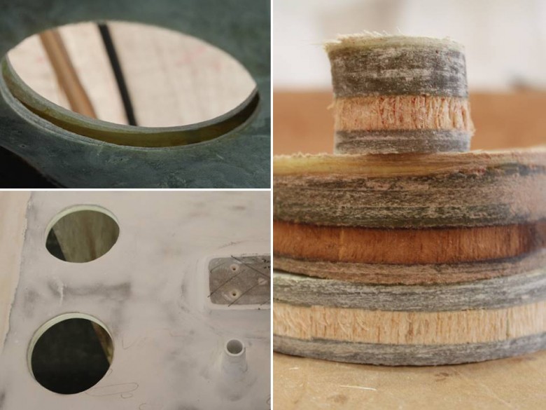
This image shows the holes that were drilled for the forward deck vents. The image on the right are good core samples of the Bristol27 deck. The layup seems quite adequate in most locations.
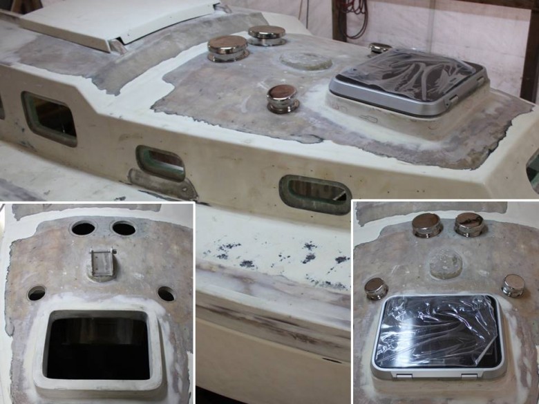
Image shows the forward deck vents placed on-deck. The forward, port vent will ventilate the composting toilet. The forward, starboard vent will ventilate the v-berth, and the aft two, large vents will ventilate the saloon.
Taking a Nap
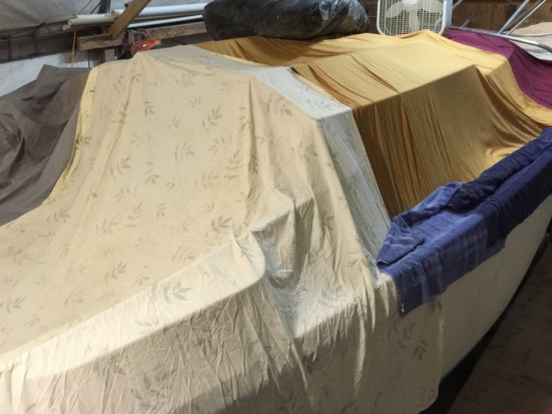
A sad sight to see, but it won’t last long. Here, the boat has been put under covers to protect the unpainted epoxy from UV damage. I can’t wait to take these blankets off and get back to boatbuilding.
Timeline
The most common question about these projects is “When will it be done?“. The answer is – as soon as possible.
While this topic was addressed in earlier news posts, it’s probably good to cover again. Early on, I tried to guess at when tasks would be done, then predict a final completion date. Later, I realized it’s nearly impossible to determine an exact timeline due to factors such as:
- Things always take longer than expected;
- Learning new skills takes a lot of time (e.g. knew nothing about boatbuilding before starting and now I’m saavy);
- Doing things the right way takes longer than duct tape solutions;
- Researching and project documentation takes a lot of time;
- Projects not receiving full attention, since my main focus and attention is on my career in the technology field;
- Social life, getting enough sleep, family and other “real life” requirements take time and are required for a healthy life.
As a point of reference, here’s what’s left on the house project:
- Pick-up work (small bits of plumbing, framing, demolition, weatherproofing)
- Windows & Doors
- Electrical
- Insulation
- Drywall
- Cabinetry
- Flooring
- Trim
- Paint
- Landscaping
Once the house projects are done, here’s the remaining high-level boatbuilding projects:
- Deadlights
- Companionway (including Seahood)
- Headliner
- All interior lockers
- Painting
- Finish woodwork (e.g. cabin sole, trim)
- Electrical
- Deck hardware
- Standing Rigging
- Running Rigging
- Canvaswork
- Fitting out (e.g. install stove, sink, seacocks, pumps, tanks, electronics, etc.)
Conclusion
The parallels between the duplex and the Bristol 27 project are hard to miss. Both projects initially started small and after pulling back the covers, fundamental issues were discovered that required major attention. There’s many ways to interpret all of this and I won’t attempt to relay all my thoughts here. What I can say is simply this – outlook is everything.
As the problems started stacking up, and the duplex turned from a simple investment into a second job, I tried to see the silver lining. For example, once these projects are completed, both the boat and the duplex will be like new, resulting in lower recurring costs, high safety, and many other benefits. Also, I’m fortunate just to have a body and brain that operates. And, I have the ability and desire to fix these issues, since some of my innate interests include boatbuilding and construction.
When I first started building boats back in 2009, I didn’t realize how much effort it would take to try to achieve the goal of long term cruising. Now, I’m older and better understand how the world works. There’ve been many ups and downs as the projects have drawn out over the past seven years. I’m not giving up on my dreams. Instead, I’m incorporating new facts that enter my worldview and enjoying the path towards getting in the water.
Thank you for following along and for your thoughts.
Leave a Reply to earl Cancel reply