Batteries
Project Logs
October 1st, 2011
I’ve added a few new images of the battery compartment today. At this point, I’ve actually already glassed in the main battery compartment pieces which will form the battery compartment (in the lower quadrant), as well as the galley/nav-station stowage lockers (the upper and outboard areas). Likely I won’t be adding much more to these areas in the too near future, because I am shifting my focus to the exterior of the boat for the time being, however it’s great to have the basic framework in.
Another good thing about waiting to move too much more forward on this area is that it will give me more time to think about how I exactly what this to all come together. The construction of the battery compartment face and surrounding lockers will set the tone of stowage for the settee, galley and nav-station. The reason for this is because the two lockers that are already framed out, are accessed by reaching over, around and under the galley and nav-station counters. This means however I decide to fully flesh out these lockers, I will need to consider how the whole system works together.
Research
- When two dissimilar metals are immersed in an electrolyte (a conductive liquid), a voltage develops. Devices that supply electric energy from a chemical reaction are known as voltaic cells. Combining two or more voltaic cells creates a battery. The voltage of a cell depends on the metals and the electrolyte. Stick a strip of zinc and a strip of copper into an olive, and you will probably measure a potential of about ½ a volt. A dry cell has a voltage of about 1.5 volts. Four dry cells are combined in a 6-volt lantern battery. There are six inside a 9-volt radio battery. Wet cells have a peak voltage of around 2.11 volts. When six wet cells are combined inside a plastic case, they become a 12-volt battery (a somewhat misleading designation since the actual fully charged voltage is about 12.65 volts). (This Old Boat, p. 265)
- For many years, conventional wisdom held that the best arrangement for batteries in house use on a boat is to have two separate battery banks, alternating between them daily. For a number of reasons explained…it makes more sense to combine all the house batteries into a single large bank. (Cruising Handbook, p. 161)
- You do need a separate battery for starting the engine, but whatever batteries you intend to use to supply your house power should be combined into a single bank…The larger the bank, the shallower the discharge for a given time between charging. Shallower discharges extend battery life. Alternatively a larger bank allows you to extend the time between recharging, reducing wear and tear and operating costs. A larger bank will also accept charge at a higher rate, allowing your charging equipment to operate more efficiently and reducing the recharge time. (This Old Boat, p. 266)
- …a [double] bank configuration leads to better battery performance, longer battery life, and higher safety. Basically, the less you discharge a battery, the better. Fast discharges are also harmful and lower available battery capacity (see Peukerts law)….Minimizing the number of battery banks maximizes battery life. Most reasonably sized boats only need two battery banks: One bank to start the engine, the other to power all other loads on board. While an emergency switch to combine them should exist (to use your house bank help start the engine if the engine bank is down), the two banks and circuits should be completely separate. (http://www.vonwentzel.net/Battery/03.Banks/index.html)
- It’s not uncommon nowadays for a 40’ cruising boat to carry a battery bank of 600 – 800 amphours. (Upgrading the Cruising Sailboat, p. 241)
- Battery types should never be mixed in use and, ideally, not mixed when recharging (although this can often be difficult to avoid). It is preferable that all batteries on the boat be the same type, from the same manufacturer, and the same age. (Cruising Handbook, p. 169 -70)
- Battery banks last longer, provide more charge: Less depth of discharge and lower rate of discharge (i.e. battery bank Amp-hour capacity vs. discharge) will make your batteries last longer in terms of cycle life and in terms providing energy. In his excellent tome on boat maintenance, the “Boatowners Mechanical and Electrical Manual”, author Nigel Calder provides convincing arguments why a large bank of cells will always outperform the constituent batteries by themselves. Ample Power and other manufacturers of charging systems come to the same conclusion.Not only will a collective bank be affected less by Peukerts Effect (the smaller the rate of discharge, the more juice you can extract from a battery or battery bank) but the depth of discharge for a large bank will be less than if a constituent battery had to carry the load alone. Depth-of-Discharge (DOD) is one of the most important variables that determines the life of your batteries. The faster, deeper you charge/discharge lead acid batteries, the shorter their life. Some things to keep in mind: (http://www.vonwentzel.net/Battery/03.Banks/index.html)
- The only caveat to large banks of batteries is proper internal fusing. If a cell shorts out in a battery, the battery voltage will drop approximately 2 Volts. All batteries in the bank will start discharging into the shorted battery, unless fuses take the bad battery out of the circuit. Thus, battery banks need to be fused internally as well as externally.
- Remember, your entire electrical system has to meet all requirements: Wires, fuses, chargers, batteries, alternators, etc.
- The ABYC requirements are a good first step in that direction and guides such as Mr. Calders are easy to understand.
- More fusing and wiring information can be found at Blue Sea Systems.
- Replaceable Batteries – Batteries must be fresh, which means that they must not be allowed to die out. A good policy is to use only one kind of battery in ship’s gear and lanterns so batteries can be inter-changed: put brand-new ones in emergency gear and recycle old ones into on deck flashlights….write the date of the installation on the cases with a marking pen. (Desirable and Undesirable Characteristics of Offshore Yachts, p. 247)
- Batteries come in all different sizes. Many have “group” sizes, which is based upon the physical size and terminal placement. It is NOT a measure of battery capacity. Typical BCI codes are group U1, 24, 27, and 31. Industrial batteries are usually designated by a part number such as “FS” for floor sweeper, or “GC” for golf cart. Many batteries follow no particular code, and are just manufacturers part numbers. Other standard size codes are 4D & 8D, large industrial batteries, commonly used in solar electric systems. Some common battery size codes used are (ratings are approximate): (http://www.windsun.com/Batteries/Battery_FAQ.htm)
Name/Type Amp Hours (AH) Volts U1 34 – 40 12 Group 24 70 – 85 12 Group 27 85 – 105 12 Group 31 95 – 125 12 4-D 180 – 215 12 8-D 225 – 255 12 Golf Cart & T-105 180 – 225 6 L-16, L16HC etc. 340 – 415 6 - Right after purchasing a battery, it must be charged, as a battery will ‘leak’ the charge. (Matt Hickey, http://tidalpool.org)
- Learn to interpret battery date codes. Or ask your retailer to make sure you purchase the “freshest” battery available. A battery that has been sitting on the shelf for extended periods can lose some of its charge and may not provide the performance you need during its first use. Long term performance probably won’t be compromised however, as the battery can be returned to its original levels of performance with either in-vehicle charging or by using an external charger. (http://www.autobatteries.com/basics/selecting.asp)
- Up to 18 months shelf life. (http://www.johnsoncontrols.com/publish/us/en/products/power_solutions/Battery_Technology_Centers/AGM/Hybrid_Vehicles_and_the_Role_of_Batteries.html)
- Inactivity can be extremely harmful to a battery. It is a VERY poor idea to buy new batteries and “save” them for later. Either buy them when you need them, or keep them on a continual trickle charge. The best thing – if you buy them, use them. (http://www.windsun.com/Batteries/Battery_FAQ.htm)
Battery Compartment
- Batteries are heavy and need to be secured carefully so that they will not go adrift and capsize in severe weather. They also must be well ventilated, as they may give off hydrogen gas, which is highly explosive, while being recharged. (Desirable and Undesirable Characteristics of Offshore Yachts, p. 125)
- …batteries should be checked daily for water level, as little crawling about as possible should be required. (From a Bare Hull, p. 154)
- The batteries need secure stowage low in the boat to keep the center of gravity down, but high enough to not get flooded with bilge water. (Cruising Handbook, p. 169)
- Batteries perform best in a cool environment and will be harmed by high temperatures, so they should not be in the engine room. However, it is desirable to keep the high-current circuits as short as possible; therefore the cranking batter should be close to the starter motor and the house batteries close to any high-output alternator and an inverter (if fitted). (Cruising Handbook, p. 169)
- Wet-type batteries must be accessible for maintenance. (Cruising Handbook, p. 169)
- All batteries must be in well-ventilated battery compartments because all can occasionally give off explosive hydrogen gas. This includes gel-cell and AGM batteries….In certain circumstances this can result in an explosion. (Cruising Handbook, p. 169)
Capacity
- If a battery is discharged to 50% of its capacity and then recharged to 75 – 80%, for practical purposes, only 25 – 30% of its capacity is usable on a day to day basis. This leads to a rule-of-thumb that the batteries on a cruising boat should have a rated amp our capacity of four times the daily load established by the energy audit (amp hour capacity is given in the battery specifications). However, a battery bank of this size is often not practical because of space requirements and weight. This leads to an acceptance of battery banks with a capacity of as little as 2 ½ times the daily load. However, compared to a larger bank, there will be a significant loss of DC system performance and reduction in battery life. (Cruising Handbook, p. 160 – 1)
- Most battery manufacturers in the US specify the amp-hour capacity based on a constant discharge over a period of 20 hours that reduces the cell voltage to 1.75 volts. This is known as a C20 rating, and by this standard a battery capable of supply 5 amps for 20 hours is rated at 100 Ah. But the same battery will not supply 20 amps for 5 hours. Why not? While a full water tank with a 30-gallon capacity yields 30 gallons regardless of how quickly you pump it out, battery capacity is more complicated because the energy is being produced by a chemical reaction going on inside the battery. The more rapidly the energy is removed, the less efficient the process. Subject the 2-hour-rated battery I just described to a 10 amp load, and the true capacity of the battery will be about 80% of rated capacity. (This Old Boat, p. 265)
- Deep-cycle batteries weight around 2/3 lb. Per amp-hour, so 600 Ah of battery capacity will weigh in at close to 400 lbs. (This Old Boat, p. 266)
- Reserve minutes are the number of minutes that the battery will supply a constant 25 amps. This rating tells you nothing about a battery that you won’t already know from the amp-hour rating…You are only interested in the amp-hour rating. (This Old Boat, p. 265)
- Boaters traditionally think of battery capacity in terms of amp-hours, but if the battery will be used to power an inverter, the reserve minutes rating can be more telling. Reserve minutes, also called reserve capacity, is the number of minutes a fully charged battery can sustain a constant load-usually 25 amps-before it is fully discharged. For a 12-volt battery, that means battery voltage will have fallen to 10.5 volts. Recalling that we divide watts by volts to get amps, supplying a 300-watt inverter load from a 12-volt battery requires 25 amps. So a battery with a reserve capacity of 120 minutes can theoretically handle this load for two hours, but the practical limit is just one hour since it is never a good idea to discharge a battery more than 50%. Running a 1,000-watt coffeemaker through an inverter will completely drain this same battery’s usable capacity in less than 15 minutes. If you plan to install an inverter, you need a battery with a high reserve minutes rating. (http://www.boatus.com/boattech/TipReserveMinutes.htm)
- Reserve capacity is the number of minutes a battery can maintain a useful voltage under a 25 ampere discharge. The higher the minute rating, the greater the battery’s ability to run lights, pumps, inverters, and electronics for a longer period before recharging is necessary. The 25 Amp. Reserve Capacity Rating is more realistic than Amp-Hour or CCA as a measurement of capacity for deep cycle service. Batteries promoted on their high Cold Cranking Ratings are easy and inexpensive to build. The market is flooded with them, however their Reserve Capacity, Cycle Life (the number of discharges and charges the battery can deliver) and Service life are poor. Reserve Capacity is difficult and costly to engineer into a battery and requires higher quality cell materials….[high quality] [c]onstruction materials….raise the Reserve Capacity of a battery and increase the battery’s Cycle Life. (http://www.dcbattery.com/faq.html)
- Battery life/longevity is a constant topic of frustration for sailors. What makes this even more frustrating is the confusion between Reserve Capacity (RC) and Amp Hours (Ah)….RC and Ah are NOT one in the same as I often see people use them interchangeably. Usually, most batteries that do not have an amp hour rating are also not usually a purpose designed deep cycle battery. Some still are, but have just not been Ah tested….A safe bet is to always by a battery with a Ah capacity rating. This ensures that the battery has been tested and rated for such. You still can use the RC/Reserve Capacity number but this number should generally be divided by two to arrive at a close Ah capacity….For example the Trojan AGM 4D battery is rated at 325 RC and 165 Ah. If you divide by 2 you would get 162.5 Ah’s. This is usually a close approximation to the Ah capacity of a given battery. RC is generally almost DOUBLE what the usual Ah rating is. On another forum, a rather astute and knowledgeable owner stated that their battery had XXX Ah’s. The reality is that this battery was never rated in Ah capacity and only in RC so this bank was nearly HALF the size it was thought to be, which could prove to be an expensive miscalculation. Mistaking RC for Ah can be a dangerous and costly mistake. You could kill your batts, and be left dead in the water. This is especially true if after removing 150 AH from a 300 RC bank, thinking you are only at half discharge, when you are actually closer to flat dead…..There are a few theories on how to determine Ah capacity from RC but none that I have found spot on. Some say to divide RC by 2 then to add 16 to that number while others just say to divide by 2. Personally I prefer to buy batteries rated for Ah capacity rather than to attempt a guess, as any guess could throw off a battery monitor or energy budget or could leave you depleting your bank beyond 50% DOD which can considerably shorten its life..If you buy a specific group size battery eg: group 24, 27, 29/31, 4D, 8D etc. and the one you’re buying has a significantly higher “rating” than others of the same physical size that should be a red flag that you are looking at an RC measurement rather than an Ah capacity measurement..(http://www.sailnet.com/forums/electrical-systems/63682-battery-confusion-amp-hours-vs-reserve-capacity.html)
- In general terms, the capacity of a cell/battery is the amount of charge available expressed in ampere-hours (Ah). An ampere is the unit of measurement used for electrical current and is defined as a coulomb of charge passing through an electrical conductor in one second. The capacity of a cell or battery is related to the quantity of active materials in it, and the amount of electrolyte and the surface area of the plates. The capacity of a battery/cell is measured by discharging at a constant current until it reaches its terminal voltage (usually about 1.75 volts). This is usually done at a constant temperature, under standard conditions of 25C (77F). The capacity is calculated by multiplying the discharge current value by the time required to reach terminal voltage.The most common term used to describe a battery’s ability to deliver current is its rated capacity. Manufacturers frequently specify the rated capacity of their batteries in ampere-hours at a specific discharge rate. For example, this means that a lead-acid battery rated for 200 Ah (for a 10-hour rate) will deliver 20 amperes of current for 10 hours under standard temperature conditions (25C or 77F). Alternatively, a discharge rate may be specified by its charge rate or C-rate, which is expressed as a multiple of the rated capacity of the cell or battery. For example, a battery may have a rating of 200 Ah at a C/10 discharge rate. The discharge rate is determined by the equation below:Battery capacity varies with the discharge rate. The higher the discharge rate, the lower the cell capacity. Lower discharge rates result in higher capacity. Manufacturer’s literature on batteries will normally specify several discharge rates (in amperes) along with the associated discharge time (in hours). The capacity of the battery for each of these various discharge rates can be calculated as discussed above.The rated capacity for lead-acid batteries is usually specified at the 8-, 10-, or 20-hour rates (C/8, C/10, C/20). UPS batteries are rated at 8-hour capacities and telecommunications batteries are rated at 10-hour capacities. (http://www.engineersedge.com/battery/capacity_battery_ratings.htm)
- Peukert’s law – presented by the German scientist W. Peukert in 1897, expresses the capacity of a lead–acid battery in terms of the rate at which it is discharged. As the rate increases, the battery’s available capacity decreases.Manufacturers rate the capacity of a battery with reference to a discharge time. For example, a battery might be rated at 100 Ah when discharged at a rate that will fully discharge the battery in 20 hours. In this example, the discharge current would be 5 amperes. If the battery is discharged in a shorter time, with a higher current, the delivered capacity is less. Peukert’s law describes an exponential relationship between the discharge current (normalized to some base rated current) and delivered capacity (nomalized to the rated capacity), over some specified range of discharge currents. If the exponent constant was one, the delivered capacity would be independent of the current. For a lead–acid battery however, the value of k is typically between 1.1 and 1.3. It generally ranges from 1.05 – 1.15 for VRSLAB AGM batteries, 1.1-1.25 for gel, and 1.2-1.6 for flooded batteries. The Peukert constant varies according to the age of the battery, generally increasing with age. Application at low discharge rates must take into account the battery self-discharge current. At very high currents, practical batteries will give even less capacity than predicted from a fixed exponent. The equation does not allow for the effect of temperature on battery capacity. (http://en.wikipedia.org/wiki/Peukert’s_law)
- Peukert Effect – the Peukert equation in its simplest form consists of several factors:
Peukerts Equation: I n x T = Cmax
I = current (usually measured in amperes)
T = time (usually measured in hours)
n = the Peukert number / exponent
Cmax = is the storage capacity of the battery measured in amp-hours at 1 ampere draw. Usually, the C/100 capacity comes close to this. Adding 10% to the 20-hour rating (also known as C/20) usually comes close also.

Available Capacity v. Amp Draw of 120v Battery using Peukert Equation
For a more accurate calculation, you need to modify the equation to account for the fact that most battery capacities are measured using higher currents than the 1 ampere draw that Peukert used. The folk at Smartgauge.co.uk have a good and comprehensive explanation on their site, with lots of examples. Thus, the equation would have to be re-written as (I x Hact / Cact)n x T = Hact, where Hact is the actual hour rating (i.e. over how many hours the battery was drawn down) and Cact is the available battery capacity (in amp-hours) at that draw. Most batteries’ storage capacity is published assuming a constant 20-hour draw, i.e. with Hact being 20. Assuming 20-hour ratings, the equation would thus simplify down to (I x 20 / C20)^n x T = 20. Either way, the available current is dependent on the rate of discharge and the Peukert exponent for the battery. The closer the exponent is to 1 (one), the less the available capacity of a battery will be affected by fast discharges. Peukerts numbers are derived empirically and are usually available from manufacturers. They range from about 2 for some flooded batteries down to 1.05 for some AGM cells. The average peukerts exponent is 1.2 though the exact number depends on the battery construction and chemistry.The following image shows the dramatic impact of the Peukerts exponent on the available capacity of a 120Ah battery, depending on the ampere draw. As you can see, the lower the Peukerts Exponent, the lesser the effect on available capacity. Note the dramatic difference in Available Capacity between the average flooded cell (n = 1.20) and a deep cycle AGM (n = 1.08) with high-current applications. (http://www.vonwentzel.net/Battery/00.Glossary/)
- All deep cycle batteries are rated in amp-hours. An amp-hour is one amp for one hour, or 10 amps for 1/10 of an hour and so forth. It is amps x hours. If you have something that pulls 20 amps, and you use it for 20 minutes, then the amp-hours used would be 20 (amps) x .333 (hours), or 6.67 AH. The generally accepted AH rating time period for batteries used in solar electric and backup power systems (and for nearly all deep cycle batteries) is the “20 hour rate”. (Some, such as the Concorde AGM, use the 24 hour rate, which is probably a better real-world rating). This means that it is discharged down to 10.5 volts over a 20 hour period while the total actual amp-hours it supplies is measured. Sometimes ratings at the 6 hour rate and 100 hour rate are also given for comparison and for different applications. The 6-hour rate is often used for industrial batteries, as that is a typical daily duty cycle. Sometimes the 100 hour rate is given just to make the battery look better than it really is, but it is also useful for figuring battery capacity for long-term backup amp-hour requirements. (http://www.windsun.com/Batteries/Battery_FAQ.htm)
- Plate thickness (of the Positive plate) matters because of a factor called “positive grid corrosion”. This ranks among the top 3 reasons for battery failure. The positive (+) plate is what gets eaten away gradually over time, so eventually there is nothing left – it all falls to the bottom as sediment. Thicker plates are directly related to longer life, so other things being equal, the battery with the thickest plates will last the longest. The negative plate in batteries expands somewhat during discharge, which is why nearly all batteries have separators, such as glass mat or paper, that can be compressed.Automotive batteries typically have plates about .040″ (4/100″) thick, while forklift batteries may have plates more than 1/4″ (.265″ for example in larger Rolls-Surrette) thick – almost 7 times as thick as auto batteries. The typical golf cart will have plates that are around .07 to .11″ thick. The Concorde AGM’s are .115″, The Rolls-Surrette L-16 type (CH460) is .150″, and the US Battery and Trojan L-16 types are .090″. The Crown L-16HC size has .22″ thick plates. While plate thickness is not the only factor in how many deep cycles a battery can take before it dies, it is the most important one.Most industrial (fork lift) deep-cycle batteries use Lead-Antimony plates rather than the Lead-Calcium used in AGM or gelled deep-cycle batteries and in automotive starting batteries. The Antimony increases plate life and strength, but increases gassing and water loss. This is why most industrial batteries have to be checked often for water level if you do not have Hydrocaps. The self discharge of batteries with Lead-Antimony plates can be high – as much as 1% per day on an older battery. A new AGM typically self-discharges at about 1-2% per month, while an old one may be as much as 2% per week. (http://www.windsun.com/Batteries/Battery_FAQ.htm)
Charging
- Experts agree that the best way to replace the energy you consume from your boat’s batteries is through a controlled, multi-stage process. Both conventional lead-acid (flooded) batteries and gel cells will charge faster and last longer if they are charged in distinct phases that take into account their chemical and physical complexities. The recommended three-stage charging process works as follows: (http://www.boatus.com/boattech/battchg.htm)
- Bulk Stage: This first stage provides a constant amperage bulk charge of 25-40% of the battery’s capacity (in amp hours, Ah) up to about 14.4 volts (14.2 for gel cells). This bulk charge will restore about 75% of the battery’s total capacity. It takes less time than tapering chargers, like ferro-resonant and SCR chargers, because the smart charger delivers greater current to the batteries which can accept greater current loads when they are discharged.
- Absorption Stage: The remaining 25% of capacity is restored at a decreasing rate. Maintaining the battery at 14.4 volts (14.2 for gel), the amperage is steadily reduced. The battery is considered fully charged when it will accept only 2-4% of its amp-hour capacity at 14.4 volts.
- Float Phase: The charge amperage has declined to 2-4% of the battery’s capacity, and voltage drops to 13.5 (13.8 for gel cells). This maintains the battery without losing electrolyte from gassing.
- Equalization: Applies to lead-acid batteries only. This fourth, manually triggered stage prevents lead-acid batteries from aging prematurely by applying a small, constant current until the battery reaches 16 volts, which dissolves the hardened lead sulfate crystals on the battery plates and prolongs battery life.
- Here’s another run down on multi-stage charging: (Ample Power Primer, p. 7)
- The Bulk Charge Step – When a charge source is first applied to a well discharged battery, charge current begins to flow, typically at the maximum rate of the charge source. If a true 40 Amp charger is connected to an 8Dbattery which is completely discharged, about 40 Amps of charge current would flow for some period of time. Because most of the charge is delivered at the maximum charger rate, the first step of the charge cycle is called the bulk charge step. NOTE: During the bulk step, battery voltage will steadily rise.
- The Start of the Absorption Step – At the instant battery voltage has risen to the maximum allowable voltage of the charge source, current through the battery begins to decline. This simultaneous event of reaching maximum voltage and the start of current decline marks the beginning of the absorption step. For instance, if the 40 Amp charger is set to 14.4 Volts, then when battery voltage has risen to 14.4 Volts, the charger will now holdthe voltage constant. Current through the battery will begin to decline. NOTE: The charger, (or alternator), is not limiting the current at this point. The battery is ‘absorbing’ all it can at thevoltage setpoint.
- The End of the Absorption Step – The absorption step should continue until current through the battery declines to about 2% of battery capacity in Amp–hours as mentioned above. Without knowing what the current is through the battery, you can’t know when it’s full. Just because that fancy charger, (or inverter/charger), has kicked out to float is no sign that the battery is full . . . there is no charger on the market that measures battery current! It’s a given, then, that you need to measure battery current to know when the battery is full. With a battery current meter, you can discover some very interesting details about the charge process. For instance, you can discover that once the charger voltage limit is reached, battery current begins to decline. If the current decline is rapid, either the batteries are nearly full, or they are NO GOOD! If the current decline is slow, then either the charge source has more output than the batteries can reasonably absorb, or the batteries are NO GOOD! Here’s where Amp–hour instrumentation is particularly valuable. Given enough time at the absorption voltage, charge current will decline to a steady–state value, that is, a low current that eitherstays constant, or declines very little. At the point where charge current has gone as low as it is going to, then the batteries are truly full. While 2% of Ah rating is close, good batteries will reach a steady state current at less than 1% of Ah rating.
- The Float Step – Once a battery is full, a lower voltage should be applied that will maintain the full charge. Depending on the type of battery, (liquid,gel), and the age of the battery, 13.4 – 13.8 Volts is appropriate as a float voltage.
- Temperature Compensation – The voltage given above are good only at F, ( C). For high temperatures, voltage will be less. It is important to charge batteries with temperature compensation.
- If you have lots of solar and wind-charging capacity, baby your batteries. However, if you rely on your engine alternator for recharging, you are likely to get better service from them drawing the batteries down more deeply. If you discharge good-quality deep-cycle batteries to an at-rest voltage of around 12 volts (but not below) between charging cycles, the positive effect on your quality of life should far overshadow any negative impact on the batteries. (This Old Boat, p. 272)
- Some electrical generating devices often do little more than trickle-charge the battery, even if they are capable of higher charging rates during periods of high wind, fast speed or direct sunlight. Trickle charging supplies about 0.1 am (100 milliamps), and tends to damage battery plates. In a deep cycle battery, the plates are stronger than in standard marine or automotive batteries, and thus are able to stand up longer to the deleterious effects of trickle-charging. Over charging can also be a problem and to prevent this, many generator makers also sell optional voltage limiters, if their product isn’t already equipped with a regulator. (Upgrading the Cruising Sailboat, p. 241)
- Overcharging causes the electrolyte to percolate, giving off hydrogen and oxygen molecules…In flooded cells, however, modest gassing is actually beneficial. The rising gas bubbles improve the charge acceptance of the battery by mixing the electrolyte, which tends to stratify when motionless. Lost molecules are easily replaced by simply adding water to the cell. (This Old Boat, p. 271)
- Lead Acid Absorption Rate – Typical absorption voltage range 14.2 to 14.5 volts, typical float voltage range 13.2 to 13.5 volts.
- To fully charge a battery requires that its terminal voltage rises to about 14.4 Volts. If permanently applied, this voltage would boil all of the electrolyte from the battery and might even cause a condition called thermal runaway. With thermal runaway, the battery gets extremely hot and may even explode, spewing acid everywhere….While 14.4 Volts is required to fully charge batteries, a voltage under the gassing potential of 13.8 Volts is necessary to prevent overcharge. Low cost regulators, such as those found in automotive alternators produce a voltage of about 14 Volts. This isn’t quite enough to fully charge a deep cycle battery. On the other hand, it isn’t high enough to immediately cause overcharge, but it does extract its toll. Did you ever notice water loss after longhours of motoring?….Proper voltage regulation is only part of the charge characteristic required by a battery. Temperature compensation over a wide range is a must–have. At low temperatures, increased internal resistance and reduced chemical activity require a higher charging voltage. High temperatures have the opposite effect. To prevent thermal runaway, applied voltage must be decreased. Thermal runaway is a problem seen with fast charge regulators which don’t use temperature sensing at the battery….Since it takes a high voltage to fully charge a battery, and a lower voltage to maintain it after a full charge, multi–step regulators and chargers have come into existence. Such devices are a vast improvement over conventional single set point regulators. Ultimate performance is offered by regulators which sense battery temperature and compensate output as a result. Temperature compensation may be your only insurance against thermal runaway. (Ample Power Primer, p. 2)
- For maximum battery life, a battery must be recharged to 100% capacity. Recharging less than 100% may result in premature battery failure. (http://www.bdbatteries.com/mcharging_procedures.php)
- Also, remember that when charging off an alternator you will rarely charge the bank back beyond 80%-85% of capacity due to time constraints and basic battery acceptance curves so this is where your solar and wind can help in a big way. (http://www.sailnet.com/forums/general-discussion-sailing-related/69354-changing-6v-12v-batteries.html)
Charging – AC Chargers
- The engine-mounted alternator is not the only device for maintaining the charge on batteries. Battery chargers convert AC input from a shore-power connection or a generator into DC power….Most battery chargers operate on the principle of maintaining a constant voltage – exactly as the voltage regulator on the alternator does – and they suffer from the same drawbacks as the regulator. The usual setting of 13.8V results in a very low rare of charge. Before the batteries are even 75% charged, the actual output of a so-called 50 amp charger will be less than 5 amps and declining…Another constant-current type is the high-output boost charger. The output can be set to a specific amperage and turned down manually when the battery begins to gas. Boost chargers require constant attention or they will cook your batteries. Most come quipped with a timer switch to prevent the charger from being inadvertently left on for too long….The best chargers match output of the requirements of the batteries, charging in steps exactly like a smart alternator controller. The output current is constant until the batteries reach about 14.4 volts, then this voltage is maintained until the current drops below some percentage of capacity – usually around 4% – when the charger reduces output voltage to around 13.3V to safely float the batteries. Unfortunately such chargers are also the most expensive, and unless you have a real need for a quick charging – maybe you are powering the charger with an onboard AC generator – the only real benefit from your substantial expenditure is likely to be the float stage. If you have limited boat dollars, spend them on something else. Your choice of a battery charger should be guided by how you will use it. For unattended dockside charging, a constant-current charger connected to a timer is likely to be your best choice. A constant voltage charger without an automatic shutoff feature, also connected to a timer, will do about the same job. The main thing is not to leave either type charging continuously for more than a day. (This Old Boat, p. 291 -2)
- If the DC output from a battery charger is not isolated from the AC input, severe electrolysis of the underwater metals on your boat and boats around yours is very likely, and in the marine environment such a charger presents a serious risk of electric shock….If the charger is UL approved, it is supposed to have an isolated transformer. (This Old Boat, p. 292)
- The boat’s internal AC system of wires and outlets should be entirely separate from the DC system. However, you may wish to add a battery charger so that your AC power charges your DC battery when you’re at the dock. In every case, you should also install a polarity indicator that will warn you if the polarity of the system has reversed itself. And, it is important to install a main shore power circuit breaker disconnect that will shut off all power coming into the boat with the throw of one switch. Each appliance should ahve its own branch circuit breaker as well. (Upgrading the Cruising Sailboat, p. 280)
Charging – AGM & Gel Batteries
- Design and chemistry differences allow good-quality gel-cell and AGM batteries to be deeply discharged repeatedly like a deep-cycle battery and to accept a fast charge like an automotive battery. Some sealed batteries will accept a charge so quickly that they can be fully charged in about 30 minutes…In deep cycle use, these are fragile batteries operating close to the edge, and they require exacting charging regimens. While their internal chemistries – primarily the substitution of calcium for antimony in the lead alloy – allow 10 times more deep cycles, their thin and closely spaced plates make them essentially automotive type batteries. (This Old Boat, p. 269)
- Gel cells in particular will not tolerate the charging voltage delivered by a standard marine alternator/regulator. You must have specialized charging equipment to operate gel-cell batteries successfully, and you cannot mix gel-cell batteries with flooded or AGM batteries aboard unless you have a means of separately regulating the charging voltages…Gel-cell batteries have an amazing tolerance for idleness (This Old Boat, p. 269)
- AGM batteries are somewhat less finicky and can be charged at the same voltage as flooded batteries, but taking advantage of the primary benefit of an AGM – rapid charge acceptance – necessitates specialized charging equipment. This must include temperature compensation…must not [allow gassing] to any extent or it will vent, permanently damaging the battery….capable of providing very high currents. (This Old Boat, p. 265)
- Neither battery [AGM nor Gel-cell] will deliver its rating if subjected to repeated high current charges… (This Old Boat, p. 265)
- The charging voltages are the same as for any standard battery – no need for any special adjustments or problems with incompatible chargers or charge controls. And, since the internal resistance is extremely low, there is almost no heating of the battery even under heavy charge and discharge currents. The Concorde (and most AGM) batteries have no charge or discharge current limits. (http://www.windsun.com/Batteries/Battery_FAQ.htm)
- …sealed recombination absorption and gel batteries are particularly sensitive to overcharging. Once moisture is removed from the battery, it cannot be replaced. Portions of the battery damaged due to overcharging are irretrievable. However, if detected early, corrective adjustments to the charging device will save the undamaged portion of the battery. Initial signs of overcharging are excessive usage of water in the battery, continuously warm batteries, or higher than normal battery voltages while under the influence of the charger. If overcharging is suspected, correct immediately. (http://www.dcbattery.com/faq.html)
- The AGM battery has an extremely low internal electrical resistance. This, combined with faster acid migration, allows the AGM batteries to deliver and absorb higher rates of amperage than other sealed batteries during discharging and charging. In addition, AGM technology batteries can be charged at normal lead-acid regulated charging voltages, therefore, it is not necessary to recalibrate charging systems or purchase special chargers. (http://www.dcbattery.com/agmtech.html)
Charging – Cycles
- Batteries in “house” use on boats are typically cycled; that is, repeatedly discharged and recharged….A deep cycle battery is needed to withstand the stresses. The are numerous deep-cycle batteries on the market, including wet-cells (the type that need topping up from time to time), gel-cells (seal, no maintenance batteries), and AGMs (absorbed glass mat, another type of sealed battery)…Different battery types are not mixed in use, and the manufacturer’s recommended charging regimen is adhered to (this may require special voltage regulators). (Cruising Handbook, p. 160)
- Even with a quality deep cycle battery, battery life is significantly shortened if the battery is repeatedly discharged much below 50% of its capacity. At the other end of the spectrum, for reasons inherent in the internal chemistry of batteries, it takes a long time to change a battery much beyond 70 – 80%. As a result, cruisers batteries are rarely fully charged (the exception is when a boat is plugged into shore power and a battery charger is left on). (Cruising Handbook, p. 160)
- Relative battery weight is a good comparative indicator of the number of cycles a battery will deliver. This is because the lead in a battery is porous. The more sponge-like the lead, the more surface area exposed to contact with the electrolyte and the greater the current the battery can deliver. However, spongelike lead is more fragile, and there is less active material, so the battery will have a shorter life. Plates constructed of denser material will deliver more cycles and generally tolerate more abuse. Denser material weighs more, so the heavier the battery relative to other batteries with the same capacity rating, the more life cycles you should anticipate. (This Old Boat, p. 269)
- As a rule, wet-cell batteries should not be discharged much beyond 50% capacity…you may want to bend this rule in real-world conditions, but you should base all of your capacity calculations on a maximum discharge of 50%….because recharging beyond about 90% requires hour sand hours of engine time, you can anticipate normally operating your batteries between a maximum charge of 90% and a maximum discharge of 50%. This reduces usable capacity to 40% of rated capacity, which gives us just 40 usable amp-hours froma 100 Ah of battery capacity. The rule we can derive is that battery capacity needs to be at least 2 ½ times consumption in amp-hours between charges. This translates to a 250 Ah battery bank to support a 100 Ah load. (This Old Boat, p. 266)
- Over – Charging – the most destructive element in battery service. Usually the boater is not aware that this is occurring as he believes his alternator or battery charger is “automatic.” Unfortunately, these automatic circuits are sensitive to voltage surges, heat, direct lightening strikes and indirect lightening electromagnetic influences and could fail or shift their calibration. When they fail, overcharging begins to effect the batteries. During overcharging, excessive current causes the oxides on the plates of the battery to “shed” and precipitate to the bottom of the cell and also heat the battery, thus removing water from the electrolyte. Once removed, this material (which represents capacity) is no longer active in the battery. In addition, the loss of water from the electrolyte may expose portions of the plates and cause the exposed areas to oxidize and become inactive, thus reducing additional capacity. (http://www.dcbattery.com/faq.html)
- Over-Discharging – a problem which originates from insufficient battery capacity causing the batteries to be overworked. Discharges deeper than 50% (in reality well below 12.0 Volts or 1.200 Specific Gravity) significantly shorten the Cycle Life of a battery without increasing the usable depth of cycle…CHARGING Alternators and float battery chargers including regulated photo voltaic chargers have automatic controls which taper the charge rate as the batteries come up in charge. It should be noted that a decrease to a few amperes while charging does not mean that the batteries have been fully charged. Battery chargers are of three types. There is the manual type, the trickle type, and the automatic switcher type. (http://www.dcbattery.com/faq.html)
Charging – Generators
- See ‘Generators‘ project page.
Charging – Starter
- A battery isolator is an electrical device that divides direct current (DC) into multiple branches and only allows current in one direction in each branch. The primary benefit of such an arrangement is the ability to simultaneously charge more than one battery from a single power source (e.g., an alternator) without connecting the battery terminals together in parallel. This is beneficial because a weak or dead battery will drain the charge from a strong battery if both are connected directly together. The disadvantage to an isolator is added cost and complexity, and if a diode-type isolator is used (which is very common) there is additional voltage drop in the circuit between the charging source and the batteries. Battery isolators are commonly used on recreational vehicles, boats, utility vehicles, airplanes, and large trucks where one battery is dedicated to starting and running the engine and another battery or batteries run accessory loads (e.g., winches, radar, instruments, etc.). A battery isolator helps to ensure that the starting battery has sufficient power to start the engine and recharge the batteries if, for example, loads on the auxiliary battery…cause it to be drained, or if an auxiliary battery fails. Isolators are also used in vehicles with large, high-power car stereos and off road vehicles to accommodate high current loads such as a recovery winch. (http://en.wikipedia.org/wiki/Battery_isolator)
- Thanks to the Eliminator, the starter battery can now be treated to a correct charge. The Eliminator is a multi-step regulator with the express purpose of tending for the starter battery. It does so by siphoning some of the current from any charge source attached to the house bank. In the process, it eliminates undercharges or overcharges typical of isolators….Isolator problems are legendary …excessive voltage drops prevent full charges without special regulators, while full charge regulators for house batteries cause overcharges on starter batteries. When a manual switch is used to charge house and starter battery together, chances are high that sooner or later the switch will be left on during discharge, bringing down the starter battery with the house bank…..The Eliminator connects between the house and starter banks, maintaining the correct charge level on the starter bank while the house bank is being charged from alternators, battery chargers, solar panels, wind generators or other charging devices. A microcomputer controls a multi-step charge process that restores a full charge without allowing overcharge. The Eliminator is fully automatic and can even be left operating when the house bank is equalized to 16+ Volts. Battery temperature sensing is standard, and protects batteries in hot or cold weather. Used properly, the Eliminator will keep any starter battery topped up and ready to crank. Isolators are usually rated at 70 Amps and up, and may seem like a better bargain, however, the Eliminator is able to limit current, as well as turn it off completely. The Eliminator also controls the direction of current flow, and determines the final voltage on the battery …temperature compensated. The Eliminator is safer, and will extend battery life and reduce water maintenance. In the final analysis, cost of ownership is less with the Eliminator than with isolators.The Eliminator reduces system complexity. Ideally, the reserve battery is used for nothing except the starter motor. All other loads are drawn from the deep cycle bank, and all charge sources are connected directly to it as well. (http://www.amplepower.com/products/elim/index.html)
- …Battery Combiner is a voltage-sensing, battery parallel solenoid which connects batteries together under certain conditions. When your batteries are being charged (above 13.1V DC), the Battery Combiner connects either two or three batteries together so they are charged simultaneously. When the voltage drops to 12.8V DC or less, the batteries are automatically disconnected from each other. This eliminates the need to change the battery switch from one setting to another while operating the boat.The Battery Combiner is easily installed with no modification to alternator wiring. One wire connects to each bank, and a ground wire goes to negative (http://www.yandina.com/acrobats/C70Manual.pdf)
- The preferred way to deal with a house bank and a separate starter battery these days is to use a voltage follower device like an EchoCharge or a DuoCharge. This little device sits between the house batteries and the start battery. When it senses a charge on the house batteries, it bleeds off some of the charging current to top off the start battery. In implementing this strategy, you’d want to connect all onboard charging devices (alternator, battery charger, solar panels, etc.) to the house battery bank. The logic here is that the start battery requires very little charging. Typically, to start a small to medium-sized diesel requires a lot of current for a few seconds, resulting in a usage of only about 1 amp hour from the start battery. This is replaced in minutes by the alternator and, unless you have fans or other devices connected to the start battery it thereafter requires only a small maintenance-level charge. If you choose to rearrange your charging systems in this manner, be sure to include a properly sized fuse on the alternator output (in your case, a 50A ANL fuse located near the house batteries). (http://www.cruisersforum.com/forums/f14/charging-a-dedicated-starter-battery-and-house-bank-46183.html)
- While I prefer a battery combiner or isolator or Echo Charger, the practice of using the battery switch will work just fine. 99% of boaters do it that way. (http://www.cruisersforum.com/forums/f14/charging-a-dedicated-starter-battery-and-house-bank-46183.html)
- The EchoCharge only draws current from the house batteries when it senses they are being charged (voltage over about 12.8); otherwise it just sits there waiting. It will not overcharge the start battery, nor will it deplete the house batteries. Operation is TOTALLY AUTOMATIC. You don’t have to switch anything in order to get charging going to the proper batteries. But you do have to wire things correctly:1. ALL onboard charging systems (alternator, solar panels, battery charger, etc.) wired to the house battery bank, with an appropriate fuse near the battery bank (ANL or terminal fuse with an AIC rating of at least 5000 amperes);2. Start battery on it’s own ON-OFF switch. The Blue Sea Systems 6006 switch is compact and inexpensive, and more than sufficient for any current you’ll encounter. (http://www.cruisersforum.com/forums/f14/charging-a-dedicated-starter-battery-and-house-bank-46183.html)
- my Heart inverter had a built-in echo-charge circuit, so I didn’t need a separate echo-charge device (http://www.cruisersforum.com/forums/f14/advice-on-adding-starter-battery-76121.html)
- I have a bluesea automatic charging relay between my house and starter; it works really well. Same idea: when there’s enough voltage (indicating a charge) it connects the banks. When the charge goes away it breaks the connection. (http://www.cruisersforum.com/forums/f14/advice-on-adding-starter-battery-76121.html)
- I will use the Blue Sea Add a Battery kit to automate the charging and still be able to use the house bank to start with if I have to. (http://www.cruisersforum.com/forums/f14/advice-on-adding-starter-battery-76121.html)
- One drawback to combiners versus echo/duo charger is if you have a 3 stage regulator. The Balmar ARS-5 in one of its programs (wet cell) uses 14.8 volts as the bulk charge limit before dropping to 14.4 in absorption mode. It stays in bulk charge mode until the duty cycle to the field coils drops below a certain percentage. If your house bank is low, the regulator could be at the higher voltage for a time, so your start battery which probably topped off in the first 15 minutes is now mostly outgassing and getting warm overcharging.Not all 3 stage chargers have a separate voltage setpoint for bulk phase. (http://www.cruisersforum.com/forums/f14/advice-on-adding-starter-battery-76121.html)
- …suggest that you connect all charging systems to the house bank. Connect both house batteries to make on large bank. Install an echo charger from the house bank to the start battery. That’s it, simple and no switches to change. You can connect the house bank and start battery to the battery switch to use if the start battery goes dead and you need an assist from the house bank to start the engine….Only thing I’d add is an ANL fuse in the starting circuit. Even though it’s not mandated under ABYC guidelines, it’s a very good idea to prevent fires. A 250A ANL should do the trick….Also not shown in the simplified diagram [see image below] are the two small inline fuses on the positive leads of the EchoCharge. While there are a couple of other ways to implement this, the way shown in this diagram will completely isolate the starting circuit from the house circuit — and avoid any voltage drop or spikes on the house circuit — and will avoid any need to change the position of the combo switch….leave it in the #1 position when you’re on the boat.And, leave the ON-OFF switch for the engine OFF unless you’re away from the dock or mooring and planning to use the engine. (http://www.cruisersforum.com/forums/f14/advice-on-adding-starter-battery-76121.html)

How to wire in an echo charger to trickle charge a starter battery.

Charging – Sulphation
- Sulfation is the result of undercharging or, more accurately, of leaving the battery in a state of discharge. Sulfates that form on the lead plates during discharge are initially soft and readily recombine with the electrolyte when a charging current is applied. But if the battery is not charged these soft sulfates crystallize in a matter of hour, becoming a hard coating on the plate and permanently diminishing the capacity of the battery. Daily charging current provided by solar panels or a wind generator can virtually eliminate sulfation. (This Old Boat, p. 271)
- Batteries are subject to an internal discharge, also called self-discharge. This rate is determined by the battery type, and the metallurgy of the lead used in its construction….Any battery discharge, including internal discharge, produces sulphation on the battery plates as part of the chemical cycle, and given enough time, this sulphation hardens, causing diminished battery capacity at best, or total loss of function. Routine charging after use, or use of a “floating” charger for long periods of storage (boat batteries, ATVs, etc.) reduces this diminished capacity and maximizes battery life. (http://www.chargingchargers.com/tutorials/battery-desulfation.html)
- Wet cells, with the cavities inside for electrolyte, use a lead-antimony alloy to increase mechanical strength. The antimony also increases the internal discharge rate to between 8% and 40% per month. For this reason, wet cells should not be left unmaintained or uncharged for long periods….A large portion (approaching 50%) of lead acid batteries have diminished capacity or become unusable due to sulphation, and never reach their rated lifespan. The lead used in Gel and AGM battery construction does not require high mechanical strength since it is stabilized by the gel or mat material. Usually calcium is alloyed with the lead to reduce gassing and the internal discharge rate, which is only 2% to 10% per month for the AGM and Gel batteries. (http://www.chargingchargers.com/tutorials/battery-desulfation.html)
- Infrequent or inadequate complete recharging can also cause overdischarging symptoms called sulfation. Despite that charging equipment is regulating back properly, overdischarging symptoms are displayed as loss of battery capacity and lower than normal specific gravity. Sulfation occurs when sulfur from the electrolyte combines with the lead on the plates and forms lead-sulfate. Once this condition becomes chronic, marine battery chargers will not remove the hardened sulfate. Sulfation can usually be removed by a proper desulfation or equalization charge with external manual battery chargers. To accomplish this task, the flooded plate batteries must be charged at 6 to 10 amps. at 2.4 to 2.5 volts per cell until all cells are gassing freely and their specific gravity returns to their full charge concentration. Sealed AGM batteries should be brought to 2.35 volts per cell and then discharged to 1.75 volts per cell and their this process must be repeated until the capacity returns to the battery. Gel batteries may not recover. In most cases, the battery may be returned to complete its service life. (http://www.dcbattery.com/faq.html)
Charging – Temperature
- All batteries heat up during the charging process, and the faster you charge, the more heat you generate. This leads to gassing… (This Old Boat, p. 269)
- During charge, a portion of the energy is converted to heat. Expect battery temperature to rise between 20F and 40F during a complete charging cycle. Gassing is directly related to battery voltage and electrolyte temperature. If the battery temperature rises to 120F, gassing starts at just 13.4 volts, but hold the battery temperature at 100F, and you delay off gassing until the battery voltage rises to 13.8. House batteries given a cool location should experience only beneficial gassing and that only near the end of the charge cycle. They will require the addition of water only occasionally. (This Old Boat, p. 271)
- …we need to establish the relationship among charging capacity, storing capacity, and consumption….how to determine how much charging capacity is enough. The maximum absorption rate of an automotive (thin-plate) battery is no more that 50% rated capacity of the battery; i.e. a 100 Ah automotive battery may accept a charging current up to 50 amps. However, a battery charged this rapidly will get hot and start to gas (bubble) by the time the battery is 50% charged. If the current is reduced to about 25% of the capacity, the battery will reach 75% of its charge before the gassing begins. To fully charge the battery, the current must be decreased to 4% or less of battery capacity. In concept this is much like pouring a carbonated drink into a glass. Pour it fast, and when the foam dissipates the glass is only half full Pour it slowly, and you can fill the glass to the top. Vigorous gassing, besides filling the battery locker with highly explosive hydrogen gas, depletes the electrolyte in the battery. Excessive heat damages the plates and separators inside the battery. Both conditions will kill a battery in short order. Deep cycles have a much slower absorption rate than the thin-pate variety. A deep-cycle battery should never be subjected to a charging current higher than 25% of it’s capacity, and even this current will cause the battery to begin gassing long before it is fully charged. This means that your total batter capacity is 100 Ah, a 25 amp alternator is all you need. A 50 amp alternator will provide the maximum charging current for a pair of 100 Ah batteries….There is a degree of inefficiency in the charging process even if you are not exceeding the level of the battery….you must replace about 20% more power than you removed to return a battery to a fully charged state. In other words, a 50 Ah will require that you put 60 Ah back into the battery. (This Old Boat, p. 285)
- Batteries are normally rated at 80 degrees, but true capacity declines with the temperature. As the temperature approaches freezing, you should expect all of these capacities to be reduced by about a third. (This Old Boat, p. 265)
- Battery capacity (how many amp-hours it can hold) is reduced as temperature goes down, and increased as temperature goes up….reduced capacity has to be taken into account when sizing the system batteries. The standard rating for batteries is at room temperature – 25 degrees C (about 77 F). At approximately -22 degrees F (-27 C), battery AH capacity drops to 50%. At freezing, capacity is reduced by 20%. Capacity is increased at higher temperatures – at 122 degrees F, battery capacity would be about 12% higher. (http://www.windsun.com/Batteries/Battery_FAQ.htm)
- Battery charging voltage also changes with temperature. It will vary from about 2.74 volts per cell (16.4 volts) at -40 C to 2.3 volts per cell (13.8 volts) at 50 C. This is why you should have temperature compensation on your charger or charge control if your batteries are outside and/or subject to wide temperature variations. Some charge controls have temperature compensation built in…this works fine if the controller is subject to the same temperatures as the batteries. However, if your batteries are outside, and the controller is inside, it does not work that well. Adding another complication is that large battery banks make up a large thermal mass.Thermal mass means that because they have so much mass, they will change internal temperature much slower than the surrounding air temperature. A large insulated battery bank may vary as little as 10 degrees over 24 hours internally, even though the air temperature varies from 20 to 70 degrees. For this reason, external (add-on) temperature sensors should be attached to one of the POSITIVE plate terminals, and bundled up a little with some type of insulation on the terminal. The sensor will then read very close to the actual internal battery temperature. Even though battery capacity at high temperatures is higher, battery life is shortened. Battery capacity is reduced by 50% at -22 degrees F – but battery LIFE increases by about 60%. Battery life is reduced at higher temperatures – for every 15 degrees F over 77, battery life is cut in half. This holds true for ANY type of Lead-Acid battery, whether sealed, gelled, AGM, industrial or whatever. This is actually not as bad as it seems, as the battery will tend to average out the good and bad times. (http://www.windsun.com/Batteries/Battery_FAQ.htm)
Charging – Voltage Regulator
- The voltage regulator is almost always the weak link in a boat’s system, limiting the available electrical power to far below the potential of the other components and shortening the life of the batteries in the bargain…Charging current should never exceed 25% of battery…but the battery will accept this maximum until it is about 75% charged. At this time the battery voltage should be around 14.4 volts, and the electrolyte should be gassing lazily. This initial stage is called the bulk charge stage. I noted earlier that mild gassing is actually beneficial to flooded batteries. At this point, the charging source should maintain a constant charging voltage of 14.4 volts and allow the charging current to decline according to what the battery can accept. This is called the absorption or acceptance charge stage. When the current drops below around 4% of battery capacity, we abandon voltage regulation and feed the battery a constant current at this low level until battery voltage stabilizes at its maximum level – typically around 16 volts. This is called equalization. Once the battery is fully charged, we want to go back to voltage regulated charge, but now we want the voltage to be held constant at around 13.3 volts. This is called the float charge stage – maintaining the battery at full charge without overcharging. In actual practice, the equalization step is usually omitted because it takes several hours to raise the battery charge from 90 – 100%. Heavy duty, deep cycle, flooded batteries should, however, be equalized periodically to maximize their performance. (This Old Boat, p. 288)
- For an image of regulator charging profiles, see image from This Old Boat, p. 289.
- …regulators intended for marine use often have the cutout voltage elevated, up to a maximum of 14.4 volts. This cuts charging time dramatically but can damage the batteries in a different way. A 14.4-volt regulator starts with a current around 40% of battery capacity…and abuses the battery for close to 40 minutes before the steadily declining current drops below the safe 25% rate. The battery reaches an 80% charge level in about 1 hour and 40 minutes, 90% in an additional hour – not much longer than the ideal – but if you continue to run the engine, the 14.4 volt setting will result in serious overcharging, boiling away the electrolyte and corroding the positive plates. Corrosion of the positive plates is the number two cause of battery death. (This Old Boat, p. 288)
- High-output regulators are not without problems. Undercharging your batteries is more damaging – not to mention frustrating – than is some overcharging, but continuing to apply 14.4 volts to fully charged batteries will definitely shorten their lives. They will tolerate being charged occasionally for several hours with a 14.4-volt regulator as long as you pay attention to their water level. But if you motor a lot, the high-output regulator will be doing a number on your batteries. A different solution is indicated. (This Old Boat, p. 288)
- Optimizing voltage regulation on cruising boats is complicated. The idea is to force-feed the batteries with the maximum charging current they can absorb without pushing this process to the point at which the batteries are damaged. This requires a sophisticated multi-step voltage regulator, such as those manufactured by Ample Technologies, Balmar, Xantrex/Heart, TWC, and Sterling. In a single alternator installation, the high-output alternator that replaces the original engine-mounted alternator will be controlled by a multistep regulator, with the charging regimen fine tuned to suit hte house batteries. (Cruising Handbook, p. 165)
- A multi-step voltage regulator does more to improve the health for the DC system on a typical cruising boat that any other device on the market. The improved charging regimen often extends the life of the batteries, with the result that the regulator may be one of the few things on the boat that almost pays for itself. (Cruising Handbook, p. 165)
- A smart controller typically reduces charging times by 25% or more if the batteries are discharged of 50% level. Perhaps more important, the charging profile is gentle on the batteries, helping to give them a long life. However, if you run your engine daily for other reasons…the actually charging profile is not likely to look appreciably different from a standard (read cheap) regulator. That is because a controller operating in the acceptance stage functions essentially as a standard regulator. Likewise, if you equip your boat with adequate solar or wind-generating capacity to satisfy most of your power requirements, you could find yourself deriving very little benefit from the considerable amount of money you will spend on a smart controller. One benefit of the smart controller that accrues regardless of your charging regime is the float stage…the engine on your boat will run far more hours than you anticipate. Cutting the charging voltage back to 13.3 keeps those long engine hours from overcharging your batteries. However, if this will be your only benefit from installing a smart controller, there are less expensive ways to achieve a similar result. (This Old Boat, p. 290)
Charging – Voltage Regulator (Alternator)
- A properly sized alternator is only one piece of the charging puzzle; just as important is the voltage regulation program. No matter the capacity of the alternator, its potential is largely wasted unless it is regulated to optimum effect. The standard voltage regulator installed inside the alternator that comes with most engines is optimized for charging cranking batteries, but is very poorly set up for charging batteries that are regularly cycled in house applications. When used on house batteries, the net effect is to unnecessarily prolong charging times (by a substantial factor), while also contributing to premature battery death. (Cruising Handbook, p. 165)
- You can waste a lot of money and effort if you don’t purchase a modern, three-stage voltage regulator to control your new alternator. If you don’t, it will never charge and maintain your batteries as well as it should…Automotive alternators and regulators are designed to charge a lot for just a few minutes and then put out just a little for the rest of the run. This is because car batteries usually don’t get discharged very deeply. Your boat is different…at least the house bank of your batteries will normally receive a substantial discharge. Therefore, in order to catch up, the alternator has to put out a heavy load when you start up….the three stage voltage regulator will improve your batteries’ life. (All in the Same Boat, p. 159)
- Our large alternator charges the batteries fast. It also uses a lot of engine power to run–a noticeable difference with and without. Therefore, there are times when we really have no need to use the alternator for charging while motoring; why waste the engine power and reduce efficiency? Because the system is set up with an external regulator, it is easy to incorporate a switch into the circuit. The regulator is powered through the ignition circuit; turning the key switch on supplies power to the regulator, which then allows the alternator to charge the batteries. If you disconnect the regulator while the engine is running, the alternator stops charging. Sure, the alternator keeps spinning, but is producing no power. Therefore, all I needed to do was install a switch somewhere so that I could turn the regulator on and off at will…With the switch installed, I ran a doubled piece of #14 AWG red wire from behind the panel, along one of my existing wire chases, and into the engine room. Once there, I connected one of the wires to the existing power supply (which runs from the ignition switch and, originally, directly to the regulator on/off spade); this wire now formed a continuous run up to behind the new switch. The other wire, which will connect to the other side of the new switch, I ran up to the regulator on/off tab and connected it with a spade connector. (http://www.triton381.com/projects/smallprojects/smallprojects4.htm)
- When a 50 amp alternator is running at the rated rpm, it puts out 50 amps – period. But we have already noted that if you have 100 Ah deep-cycle battery, you never want to charge it with a current greater than 25 amps. And as it approaches full charge, the charging current should decline to a tenth of that level. Limiting the output current of the alternator is the job of the voltage regulator. It works much like a thermostat, only instead of sensing room temperature, it senses battery voltage. When the voltage is low, the regulator turns on the spinning alternator by passing current to the field winding. The now charging alternator raises the voltage in the charging circuit to a preset level – typically 13.8 volts for an automative regulator and up to 14.4 for a marine regulator. When the voltage reaches this level, the regulator senses this drop in voltages and turns the alternator back on. In a solid state regulator this off-and-on switching takes place hundreds of times per second, and the output current is an average of current pulses such switching causes. As the battery voltage rises, it takes progressively less time for the alternator to elevate the voltage in the charging circuit to the cutout voltage. The “on” times become shorter and shorter, lowering the level of current output from the alternator. (This Old Boat, p. 287)
- Alternator Controllers – Instead of regulating alternator output by pulsing the field current (switching it on and off), it can also be controlled by setting the field current to a specific level. [There are manual and smart controllers, these days only the smart controllers are the way to go]. [smart controllers have] a computer chip integral to the controller monitors voltage and increases or reduces alternator output as appropriate to maximize the charge level and minimize the charging time. Beyond some initial program choices when the controller is first installed, no manual intervention is required. Smart controllers generally operate in three distinct steps: (This Old Boat, p. 290)
- Initially the controller induces the alternator to provide a constant current of around 25% battery capacity, but the level may be adjustable or at least selectable.
- When battery voltage rises to around 14.4 volts…the controller abandons current regulation in favor of voltage regulation, holding the charging voltage at 14.4. This allows the battery to accept current at its natural rate. The acceptance phase continues until the current declines to around 2% of capacity, or it may be terminated by the controller based on time. Either way, the charge level should approaching 90%.
- Then the controller cuts the voltage back to around 13.3 volts and holds it there so the batteries will not be overcharged if the engine continues to run. Many, but not all smart controllers also have the ability to include the equalization phase, holding the output current fixed at 4% or less of battery capacity until voltage rises to around 16 volts. Equalization is generally on demand and probably not particularly beneficial more often than every 50 cycles. Equalization is only appropriate for deep-cycle batteries.
- Dual Regulators – One alternative is two regulators. Solid-state regulators are relatively inexpensive. Connecting two of them in parallel one with a 14.4-volt setting and the other with a 13.3-volt unit, will allow you to select the charge voltage. This is accomplished with a switch in the field wire from the 14.4-volt regulator. When the switch is closed, the higher alternator output called for by the 14.4-volt alternator exceeds the cutout voltage for the other regulator, essentially turning that regulator off. When the switch is open, the 14.4-volt regulator is off-line and alternator control is taken over by the lower-voltage regulator. Unfortunately you may have difficulty finding a 13.3-volt regulator…a common 13.8-volt regulator will probably do a yeoman’s job. The reason for this is that almost all regulators are temperature compensated, losing as much as 10 millivolts (0.010 volt) per C increase in temperature. So if the regulator is mounted in the engine compartment and the temperature there rises by 30 – 40C – not unlikely given the long run times we are attempting to accommodating – the charging voltage declines to 13.5 or 13.4, low enough that any overcharging is likely to be inconsequential. (This Old Boat, p. 290)
- Adding Resistance in Sensing Wire – Another way to skin the same cat is through deception. If we had resistance to the sensing wire of the regulator, we fool it into thinking that the voltage in the charging circuit is lower than it actually is. As a result the regulator compensates by increasing the alternator output. This ploy is particularly applicable for an alternator with internal regulation, and it can satisfy two objectives. If we size the resistance to cause a 0.6V drop in the sending wire of a 13.8V regulator, it will behave like one set to 14.4-volts, the charge voltage we normally want to see from our alternator. However, a simple switch around the resistance takes it out of the sensing circuit, re-establishing 13.8 volts as the cutout voltage. In concert with a hot engine compartment, this reduces or eliminates the risk of overcharging while motoring. The best way to establish the desired voltage drop is with a diode rather than a resistor, because the level of the drop is unaffected by the magnitude of the current flowing through the wire. Conveniently the typical voltage drop through a silicon diode is around 0.6V, just the drop we need. A specific diode that will serve is an IN6500 or the equivalent. Current in the sensing wire flows toward the regulator, so be sure the cathode end (the marked end) of the diode is on the regulator side of the circuit. (This Old Boat, p. 290)
- Field Disconnect Switches – if this seems too complicated, just replace your existing regulator with a 14.4V unit and protect against overcharging with a simple field-disconnect switch. A switch installed in the field wire (not in the sensing wire) interrupts power to the alternator field, turning the alternator off. The 14.4V regulator will provide good charging performance – only 20 – 25% off the pace of the best smart controller – and if you find yourself with full batteries and still motoring, just flip the switch. There is a lot to be said for simple and cheap. (This Old Boat, p. 291)
- Balmar Smart Ready Internal Regulation – Small case 6-Series alternators are uniquely constructed with Smart Ready Internal regulation to provide two options for operation. Used alone, the 6-Series alternator can deliver higher output than standard factory alternators with the simplicity of basic, single-stage regulation. When used in conjunction with a Balmar multi-stage voltage regulator, the 6-Series alternator can provide larger flooded deep cycle, gel, AGM and spiral wound battery banks with the intelligent charging characteristics required to provide battery care in league with smart shore power chargers. (http://www.balmar.net/PDF/alternator%20info/6-series-sheet-web.pdf)
- The voltage regulator maintains voltage at a certain level by matching alternator output with the load and the charge level of the battery. Voltage drops when a load is placed on the power system, or when the battery discharges. The regulator then increases the amperage output of the alternator until the voltage level is restored, and then tapers output to a level that will sustain that voltage. You should have a regulator that is external, field adjustable, so that you can tailor the settings to your specific power needs and charging patterns. If your engine running time is minimal, you may need a high setting, like 14.4 volts, to get the fast charge you need without damaging your batteries. If you run your engine for extended periods, 13.8 volts may be adequate. (www.boatus.com/boattech/12volt.htm)
Monitoring
- See the ‘DC System‘ project page for information on monitoring batteries.
Type – AGM & Gel Cell
- In practice sealed batteries are often better suited to power-usage patterns on cruising boats that are not hooked up to shore power on a routine basis. Because they recharge more quickly, suffer neglect more easily, and are much less susceptible to environmental damage, they in many cases have longer useful service life than poorly maintained wet-cell batteries. (The Modern Cruising Sailboat, p. 228)
- Pro – doesn’t offgas, doesn’t need to be ventilated. AGM batteries main advantages are no maintenance, completely sealed against fumes, Hydrogen, or leakage, non-spilling even if they are broken, and can survive most freezes.
- Con – weighs more, needs to be charged correctly or could be killed (but easily charged correctly though by modern battery charger – solar, engine)
- Gel-cell batteries derive their name from the form of the electrolyte used, which has the consistency of butter rather than water. Absorbed glass mat batteries are a more recent offshoot of the same idea, but an AGM battery captures liquid electrolyte in microporous separators between the metal plates. (This Old Boat, p. 269)
- AGM (Absorption Glass Mat) sealed battery technology was originally developed in 1985 for military aircraft where power, weight, safety, and reliability were paramount considerations. AGM battery technology has continued to develop and offer improvements over other sealed battery technologies. AGM technology has become the next step in the evolution of both starting and deep cycle sealed batteries for marine, RV, and aviation applications. This “next generation” technology delivers increased safety, performance, and service life over all other existing sealed battery types, including gel technology. (http://www.dcbattery.com/agmtech.html)
- Generally, gel and AGM batteries have about 20% less capacity, cost about two times more, and have a shorter cycle life than comparable flooded lead acid batteries. However, Gel and AGM batteries do not need watering, are safer (no acid spilling out), can be placed in a variety of positions, have a slower self-discharge characteristic, and are more efficient in charging and discharging than flooded batteries (see table below). Gel batteries are more suitable for deep cycling applications whereas AGM batteries are more for light cycling and engine-starting applications. (http://www.plasticclassicforum.com/forum/)
- For me the benefits of AGM rank in this order: (http://www.plasticclassicforum.com/forum/)
- Higher acceptance – This is a HUGE benefit IF you can take advantage of it, many AGM equipped sailors I know physically can’t take advantage of this feature.
- Low self discharge – This is great for boats in hot climates or on moorings. Wets can self discharge at up to 13+% per month in warm weather however I know few boaters who go a month without using the boat at all. Even in a worst case scenario, 13%, in hot weather leaves a full bank still at 87% SOC after a month. Still this can be a good benefit in certain use situations. Self discharge has never been an issue for me so would not be weighed in my own benefit analysis.Many boaters I know with AGM’s also have either solar or wind making the self discharge benefit mostly irrelevant. The majority of boaters in the US are on docks not moorings so again self discharge would be of little benefit to them. When off cruising you are using the banks daily and self discharge is again a non issue. Most boaters have a phantom load such as a bilge pump, stereo memory or LPG detector etc. so there are already loads sucking the battery down that require periodic charging anyway which would take care of any self discharge at the same time. If you don’t have solar or wind, are on a mooring, in a hot climate and rarely use your vessel this can certainly be a benefit.
- Maintenance – I find this to be a tad over blown. I have yet to work on a vessel where it took me more than 20-30 minutes to add water to batts or check them and those are the long ones with major access issues. My own batts at 4 years old have taken water just twice now and it took all of about 3 minutes each time maybe four minutes at the outset if I got ADD..If maintenance is the sole claimed reason for “upgrade”, I know a boater who did this for that exact reason, it really is a lot of money to spend. He could have paid a pro to do the maintenance and still pocketed $400.00 to $500.00. Wet cell maintenance gets a little over blown IMHO and experience plus for very little money one can buy hydrocaps if really concerned.Our batteries are dumb regulated and reside on a rather un-sophisticated solar charge controller yet they took a very small amount of water just twice in four years. I honestly don’t even consider that “maintenance”. Just checked them before winter and with my screw driver it took me all of 1 minute to glance at the water levels.Even if I gave the water filling a ten minute labor allowance every year, at my $70.00 hourly rate, that is $11.60 worth of labor time. I would have to add water to my batteries 61 times over their life to equal the price premium on my bank to make the move to AGM based on maintenance alone.
- Lay on side – This is usually much more of an issue on smaller vessels than large and folks with smaller vessels often won’t spring for AGM’s anyway. For about $40.00 in materials one can build a battery platform on just about any vessel. I have done them on nearly every boat I have owned for far less than the premium price upgrade to an AGM battery. You still have to find a way to secure them so you would possibly be looking at some epoxy work anyway.
- Here’s a guide for charging AGM optima batteries as an example of how an AGM might be charged: (http://www.optimabatteries.com/product_support/charging.php)
- Alternator – 13.65 to 15.0 volts, no amperage limit
- Battery Charger – 13.8 to 15.0 volts, 10 amps maximum, 6-12 hours approximate. Always use a voltage regulated battery charger with limits set to the above ratings.
- Cyclic Applications – 14.7 volts, no current limit as long as battery temperature remains below 125°F (51.7°C). When current falls below 1 amp, finish with 2 amp constant current for 1 hour
- Float Charge – 13.2 to 13.8 volts, 1 amp maximum current, time indefinite (at lower voltage).
- Rapid Recharge – Maximum voltage 15.6 volts (regulated), no current limit as long as battery temperature remains below 125°F (51.7°C). Charge until current drops below 1 amp.
Type – Starter
- To be viable, a single house bank must be combined with an almost bulletproof method of ensuring an ability to crank the engine Because it must be assumed that at some time the house bank will be discharged to some point at which it cannot crank the boat’s engine, the single house bank must be combined with a separate battery reserved solely for engine cranking, and always kept in a state of full charge. (Cruising Handbook, p. 162)
- It also will not hurt to keep the starting battery out of the engine compartment, although if 100 ears of automotive experience count for anything, you should be able to mount the starting battery in a well-ventilated engine space without notable effect. (This Old Boat, p. 271)
- A heavy-duty or deep-cycle battery should be reserved for the engine, so that running appliances won’t wear down your engine-starting battery. (Upgrading the Cruising Sailboat, p. 241)
- CCA nor MCA provides any useful information for batteries used aboard a boat unless the battery will be used exclusively to start the engine. Even then, the primary value is to compare batteries for purchase. (This Old Boat, p. 265)
- Automotive batteries are fine aboard boats to start the engine, but if this type of battery is connected to your house bank with a paralleling switch and…you use it for your house loads, the deep discharge will damage it. Deeply discharged automotive batteries can fail in as few as 20 discharge cycles, making this type of battery unsuitable for even occasional house duty. (This Old Boat, p. 265)
- Starter Battery Benefit: (http://www.vonwentzel.net/Battery/03.Banks/index.html)
- Your starter bank is always full: While starting engines requires a lot of power, the burst is relatively short. Thus the net drain on your starter battery is small and even a short commute out of the harbor will pretty much replenish the charge that had been used to start the engine.
- If you accidentally run the house bank flat, you can still start the engine and recharge the house bank.
- Your electronics will behave better: When the starter and the house banks are completely separate your electronics and other circuits will not experience the voltage transients that starting an engine produces. For example, our electronics would drop out every once in a while during engine starts, suggesting that the voltage levels on board dropped below the 10V threshold that the instrument and GPS package could still run on.
- True deep cycle batteries will perform well as cranking batteries, however, cranking batteries will not survive deep cycle use. Deep cycle batteries can be used in any application and exhibit a long service life, while cranking batteries are limited to starting applications only. Cranking batteries exhibit poor service life in cycling applications. (http://www.dcbattery.com/faq.html)
- a spare battery that will always be fully charged in case you ever need it. Because no power is ever drawn from it, there is no wear: it will outlive your engine and probably the boat as well. (http://www.boatdesign.net/forums/onboard-electronics-controls/1-2-batteries-40891.html)
Type – Liquid Electrolyte (aka Wet Cell)
- The deep-cycle, lead-acid storage battery with its heavy plates, as opposed to the standard automotive type, is the best type of battery to run most sailboat accessories. Each time a battery is drawn down and recharged, tiny amounts of unwanted material build up on the plates. This process is called sulfation. Some of it flakes off and drops to the bottom of the battery case. Eventually, there is so little lead left in the plates that a small discharge current exhausts them, or so many sulfation flakes build up that they connect negative and positive plates and short-circuit the batter. In either case, the battery must then be rebuilt or replaced. (Upgrading the Cruising Sailboat, p. 241)
- All 12-volt batteries are lead-acid batteries, meaning that they are composed of lead plates and lead dioxide plates submerged in a sulfuric acid solution. Lead acid batteries are called storage batteries because they appear to store electricity. Actually the electricity is produced by an internal chemical process – as in every other battery. What distinguishes a storage batter is that you can reverse the chemical process by passing a current back through the battery, restoring it to its fully charged state. Among lead acid, there are three types that you should be aware of…[Automotive, Deep Cycle, & Sealed Valve Regulated (SVR)] (This Old Boat, p. 266)
- Deep-cycle battery…is designed to be deeply discharged over a period of time before requiring a recharge. The thicket plates reduce the amount of time that a deep-cycle battery can supply very high currents…but they allow the battery to be deeply discharged without damaging it. If a first quality deep-cycle battery is not discharged below about 50% of its rated capacity, it may be discharged and recharged as many as several thousand times. (This Old Boat, p. 265)
- 6-volt deep-cycle batteries intended for golf carts and industrial electric vehicles merit special mention because of their economy. These batteries are designed to be discharged all day, then recharged so they can do it all again the next day – pretty darn close to how sailors use house batteries. There are way more golfers than sailors, and 6-volt golf cart batteries are manufactured by the millions….that drives down the price….given basic care – which means keeping the water topped off and not allowing the battery to sit in a discharged state – good quality golf cart batteries should deliver 4 – 5 years of dependable service. They also have the comforting quality of lowering the price tag should some killing misfortune befall your batteries. (This Old Boat, p. 268)
- Most boatowners will be best served by flooded batteries…Flooded batteries require no additional expenditure for special charging or regulating equipment (although you may want to eventually add such gear for better charge performance). They are more tolerant of chronic over-charging, a typical consequence of long engine hours. For the same expenditure, you can expect flooded batteries to last 4 times as long as gel cells or AGMs. Alternatively, you can spend ½ as much on golf cart batteries and still expect twice the battery life. In use, the contrast is likely to be even greater because perhaps ½ of all SVR batteries taken aboard die an early death due to some charging impropriety. (This Old Boat, p. 269)
- Measuring Speficity Gravity & Wet Cell Batteries – The specific gravity (SG) of a liquid is its density compared to that of water. Since water is the standard, it has a specific gravity of 1.000. The specific gravity of sulfuric acid is 1.830. The water-acid mix that is the electrolyte in a flooded battery will have a specific gravity of around 1.265, but the acid ges used up during discharge, so the Sg declines toward 1.000. Between fully charged and fully discharged, the decline is around 150 points and is linear, so an SG reading of 1.250 indicates a 10% discharge. Checking specific gravity requires a battery hydrometer….you want the kind with a little glass man-overboard pole. With the battery caps open, squeeze the bulb, stick the flexible tip into a cell, and ease your grip slowly back to draw enough electrolyte up into a clear tube to float the little overboard pole….The primary advantage of assessing battery condition with a hydrometer is that it tells you the condition of each cell. A healthy battery will give consistent cell-to-cell readings. If the readings vary by more than 15 points (0.015) , the battery needs to be given a full charge, perhaps even a conrolled overcharge – called appropriately, equalizing. If any SG reading varies from the others by 50 pints when the battery is fuly charged, that cell is failing and the battery should be replaced. (This Old Boat, p. 270)
Links
- Batteries on Triton #381 – http://www.triton381.com/projects/restoration/batteries.htm
- Battery Comparison – http://www.windsun.com/Batteries/battery_comparison.htm
- Battery Technology – http://www.boatdesign.net/forums/boat-design/batteries-new-battery-technologies-21869.html
- Deep Cycle Battery FAQ – http://www.windsun.com/Batteries/Battery_FAQ.htm
- Deep Cycle Batteries Wiki – http://en.wikipedia.org/wiki/Deep_cycle_battery
- Defender Rundown of various batteries – http://www.defender.com/html/chargers_inverters_info.html
- AGM v Wet Cell Batteries – http://www.vonwentzel.net/Battery/01.Type/index.html
Charging
- Trickle Charging Wiki – http://en.wikipedia.org/wiki/Trickle_charging
Voltage Regulators
- Blue Sea Field Disconnect Switch – http://bluesea.com/viewresource/91
Type – AGM & Gel Battery
- Gel v AGM Battery – http://www.batterystuff.com/kb/articles/battery-articles/gel-vs-agm.html
- Lifeline AGM Batteries – http://www.lifelinebatteries.com/marinebatteries.php
- Windsor White Paper on AGM Batteries – http://www.windsorind.com/Upload/MarketingDocuments/5a762581-5e04-4ab8-b925-eda75a3a5706_AGM%20Battery%20White%20Paper.pdf
Type – Starter Battery
- Not using a starter battery – http://www.cruisersforum.com/forums/f14/engine-starting-video-real-world-amp-load-data-19981.html
- Selecting the right battery – http://www.autobatteries.com/basics/selecting.asp
Type – Wet Cell / Lead Acid Battery
- Lead Acid Battery Wiki – http://en.wikipedia.org/wiki/Lead-acid_battery
Image Gallery


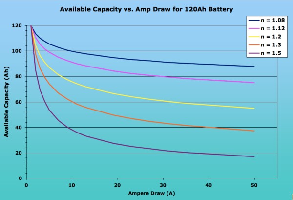


Comment Form