Engine Compartment
Project Logs
November 22, 2011
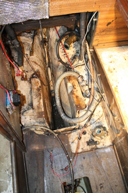
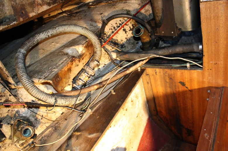
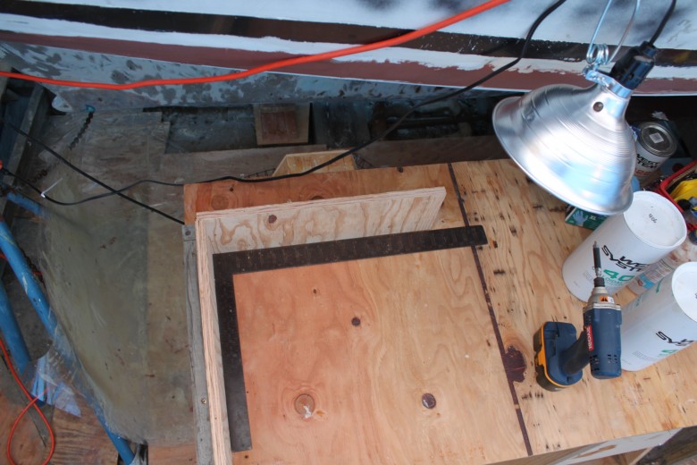
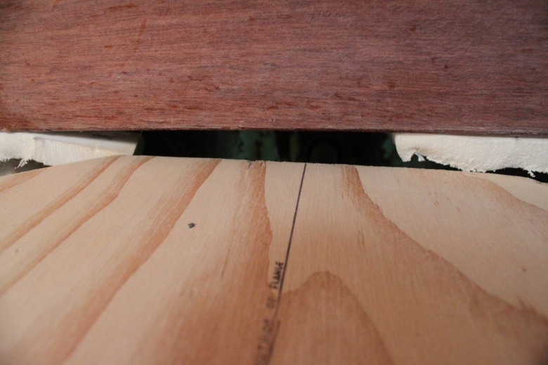
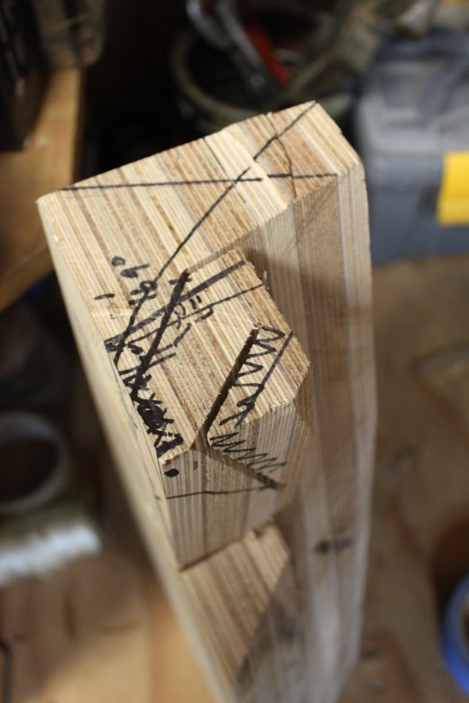
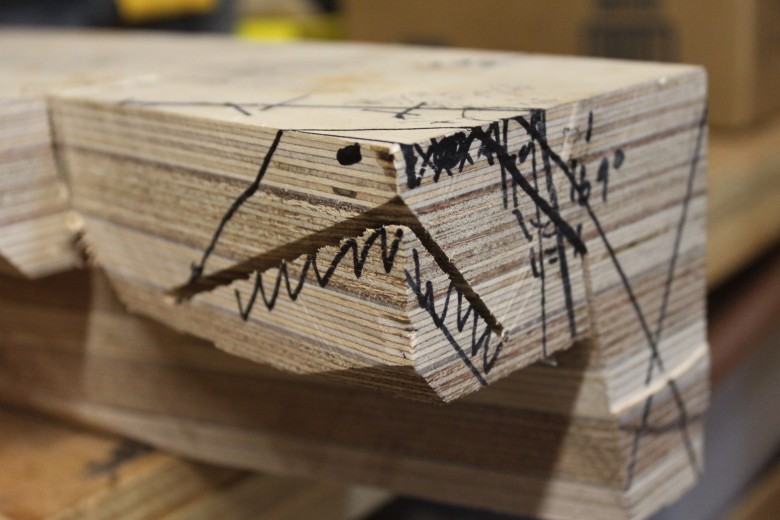
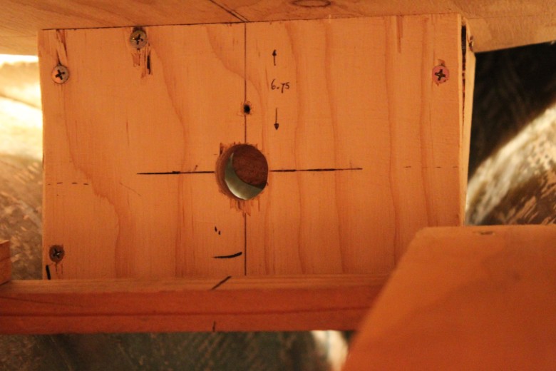
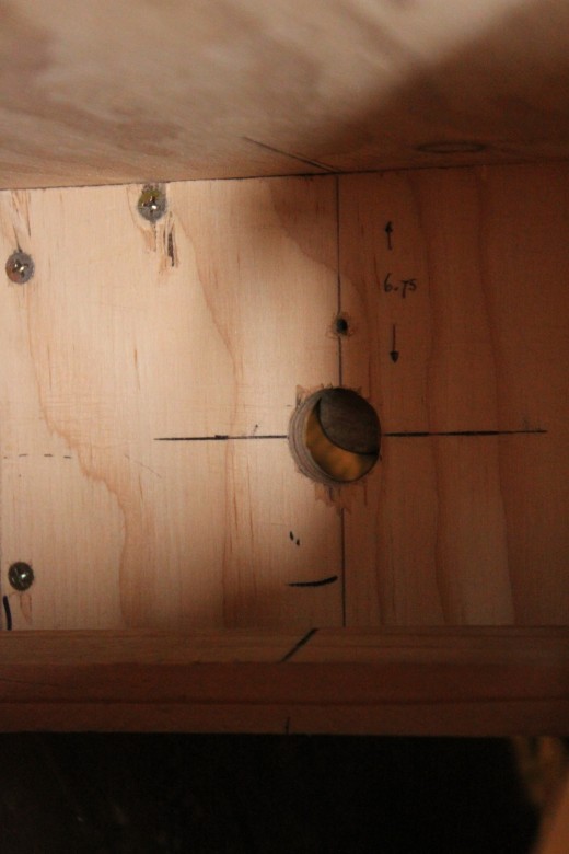
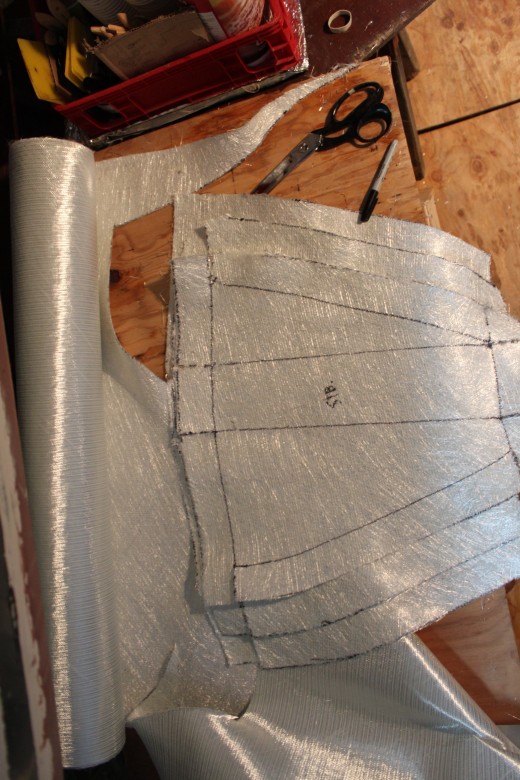
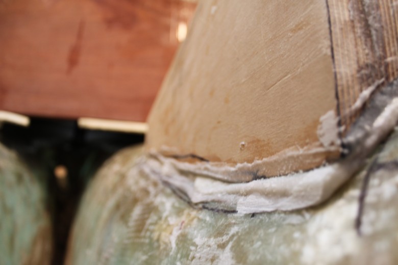
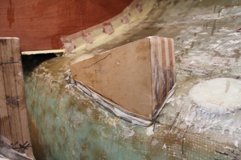
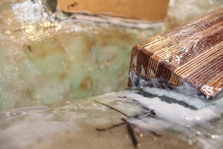
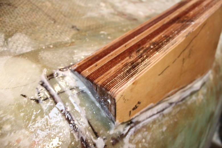
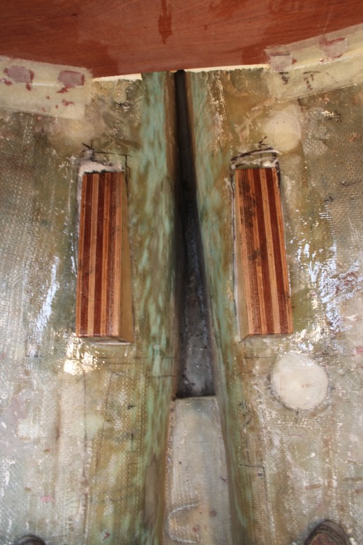
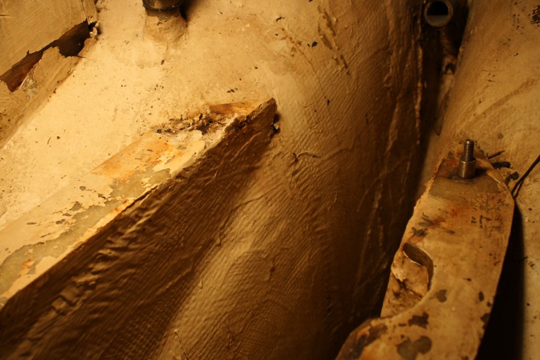
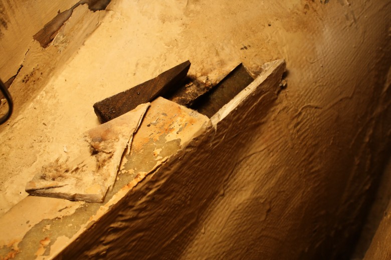
A few weeks ago, I installed a final piece to the bottom of the cockpit bulkhead. This piece has a hole cut in it for the prop shaft, as well as drainage at the bottom and it will serve as a way to keep the sound in the engine room. Here’s what the piece looked like after it was all installed:

The cockpit extension piece is installed. Note the PVC drains and hole cut for the prop shaft.
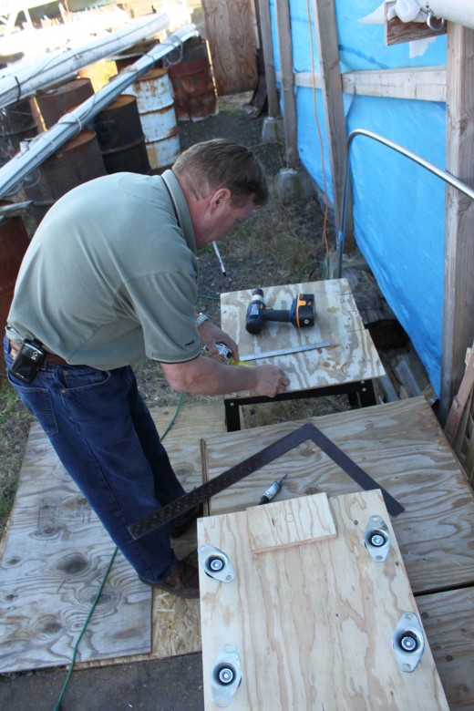
And here’s the basic process for installing this piece:
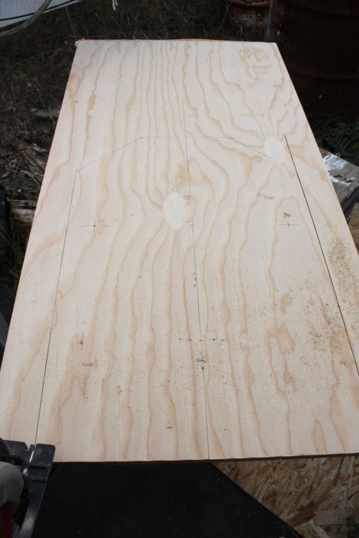
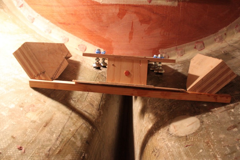
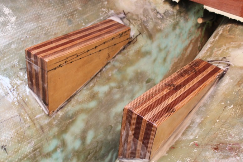
- Template the piece. It must fit below the cockpit bulkhead and inside the bilge. Somewhat of a “v” shape.
- Use the template to cut the piece, then trim any final areas that need it to finalize the fit. Also cut a hole for the prop shaft and drainage tubes
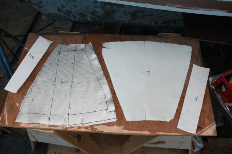
- Cut fiberglass tape for the new cockpit bulkhead extension
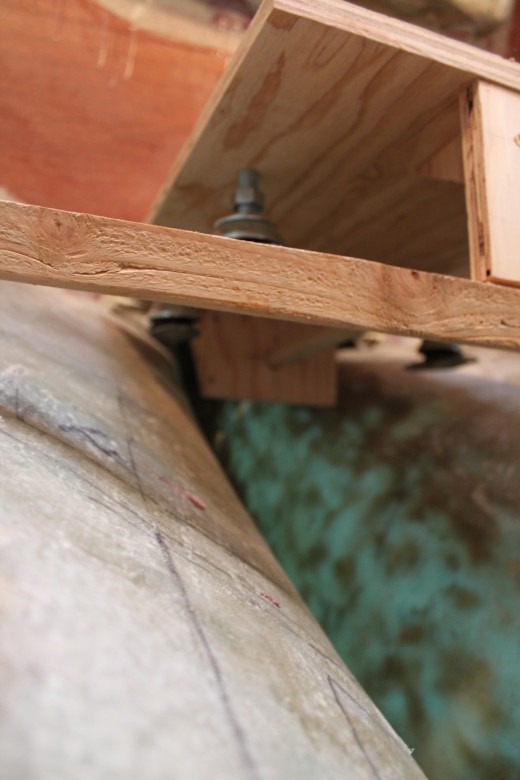
- Thicken the piece in place by thickening between the piece and the hull, then
- While the filet was still wet, I installed tabbing on both sides of the piece. First 4″, then 6″.
I decided not to use foam between the hull and this piece. My thinking is that the boat won’t flex much down in the bilge and I’ll have a very strong bond with the epoxy and fiberglass tabbing. I suppose time will tell!
2010/2011
I installed the engine mounts, settee’s and cockpit bulkheads to build the basic engine compartment. Later, I built a diesel tank in the bilge from epoxy and fiberglass. Later, I will finalize the engine compartment construction.
Research
- If you’re looking for a regulatory or “official” guidance for clearances, there isn’t any from ABYC, USC, or CFR…In general, leave as much room as you can. Practically speaking, figure on a few inches everywhere, and only reduce it if it’s critical. Don’t allow anything to touch the engine anywhere. (http://www.plasticclassicforum.com/forum/)
- I have often seen panel insulation carved out in an area to allow clearance for a belt pulley. While I think this is too close and would prefer a minimum of 1″, the point is that there isn’t any particular information to guide how close you build your enclosure. Make sure no hoses or wires rub on anything, and remember that the engine and anything connected to it moves when in operation. (http://www.plasticclassicforum.com/forum/)
- Be sure to leave adequate clearance around your exhaust manifold and riser, as these get hotter than the other parts of the engine. Usually, the clearance isn’t as much of an issue at the aft end, but obviously you don’t want combustible material to be overly close to these parts. A few inches is commonplace. (http://www.plasticclassicforum.com/forum/)
- The engine must have tender loving care, and that means good access so that you can easily change the oil and check the oil level, the water strainer, the belt drives, the shaft packing gland, and all the other important items. If you don’t have easy access, you won’t perform even the minimum maintenance. (Desirable and Undesirable Characteristics of Offshore Yachts, p. 239)
- It is especially important to be able to reach a lost tool in the bilge. (Desirable and Undesirable Characteristics of Offshore Yachts, p. 239)
- A good installation will provide the engine with plenty of air space, and with a freshwater cooling system using a heat exchanger so that the engine never comes in contact with salt water.
- one commonly accepted measure of a well-installed engine is that following: it should be capable of being operated safely and efficiently on either tack at an angle of heel not less than 28 degrees for at least 2 hours. That is another way of saying that you should be able to charge batteries in a gale of wind without worrying whether the engine will overheat and burn out.
- A diesel is a simple, clean machine and its room can be kept immaculate with a little forethought. Do not try to utilize every square inch above and around the engine for storage. It is a good idea to have spare parts readily accessible, but you will have to get at every part of the engine sooner or later, so it is best to leave open space around it. If possible, leave room above the engine so that you can crawl over it and get to the stuffing box in any seas. (From a Bare Hull, p. 154)
- Access to the engine room is also critical. you may have to get in very quickly. I’ve seen companionways that dismantle into pieces which, of course, fly about with great abandon in a seaways as soon as you remove them. The best solution is a ladder that hinges up and hooks to the cabin top. (From a Bare Hull, p. 154)
- laid out that they are also readily available and accessible…should be the drop stick to check the oil in both the transmission and the engine itself (From a Bare Hull, p. 154)
- …there are some real screw-ups on the market, including boats in which…the stuffing box cannot be serviced without removing the engine from the boat…the starter motor cannot be removed without cutting up structural bulkheads….The more it is intended to cruise a boat, the more important it is to have decent access to all the service points…Specifically, access for the following tasks must be considered:
- changing all belts
- tensioning alternator belts
- draining the primary fuel-filter bowl
- changing all filters (fuel and oil)
- checking the dipstick and pumping out the engine oil
- pumping out the transmission oil (this is tough on many boats)
- bleeding the fuel system and injectors
- checking and cleaning the engine and other raw-water filters
- changing the raw-water pump impeller
- replacing zinc pencil anodes in the heat exchanger and elsewhere
- cleaning the raw-water side of the heat exchanger
- cleaning the vented loop on the raw-water injection line into the exhaust
- checking the exhaust elbow and injection nipple
- draining water from the block and heat exchanger when winterizing
- checking the coolant overflow bottle
- accessing the engine feet to set alignment
- setting valve clearances, pulling injectors and other “top-end work
- removing the starter motor
- adjusting and lubricating the engine and transmission controls
- inspecting and adjusting the shaft seal (Cruising Handbook, 209 – 10)
- Prevent chafing in the engine room
- Have a pattern of checking my engine each time I start and stop it. I randomly run my eye and hand around various spots. It is amazing how simple vibration can chafe through water hoses, fuel hoses, improper propane lines and electric wiring. (All in the Same Boat, p. 117)
Motor Mounts
- I will be installing a Beta diesel in my Cheoy Lee Frisco as soon as the weather warms up. I drilled oversize holes for the engine mounts into the fiberglassed teak stringers and filled the holes with West System epoxy and then inserted stainless lag bolts. I coated the lag bolts with a car past wax to prevent the epoxy from bonding to the bolts so that I could remove them. Later, when dry fitting, I noticed that a couple of the lag bolts did not feel like they would tighten down with any authority, and were perhaps stripped….inserts I’ve used have a 9/16-12 (note: originally this read 9/16-24, which was incorrect) external thread, for which I tap the hole in the wood using the appropriate tool. I set them in epoxy during final installation. (http://www.plasticclassicforum.com/forum/)
- Epoxy is dandy stuff but does not really bond to steel; it bonds to the unevennesses on the steel. Also, the steel will expand and contract with temperature, a cyclical source of which is bolted thereto; the wood and epoxy beds will be expanding and contracting with moisture…HOWEVER, there’s an answer to this… MetlWeld Epoxy Adhesive MetlWeld is a super tough epoxy adhesive designed to bond metal and other dissimilar materials such as stainless steel, galvanized steel, aluminum, copper, glass, ceramic neoprene rubber and most porous services. Features: It will cure at temperatures as low as 50°F, MetlWeld will bond metals to metal, wood, stone, concrete, and even glass (http://www.plasticclassicforum.com/forum/)
- When I make up stringers I use a stainless angle. I drill holes for the engine mounts and weld nuts onto the under side of stringer to bolt the motor mounts onto. Since these are going onto existing stringers there is always a strip of metal embedded into the old stringers that I drill and tap, that way I can bolt the new stringers on using two 3/8″ bolts along with epoxy. be sure to use oversized washers or another alum. plate for a backing plate for the horizontal bolts – Definitely glass in. L Bracket distributes the load to a larger area which is a good thing. Inserts are very localized pinpointing all that torque into four/eight fairly small areas. (Ben Thomas, Beta Dealer)
Sound Insulation
- Constant velocity couping between the engine and the shaft. This type of coupling tolerates a large amount of misalignment and reduces problems with the packing gland. (Desireable and Undesireable Characteristics of Offshore Yachts, p. 241)
- The engine should be installed on soft mounts, which reduce vibraton and noise transmission into the hull and propeller. (Desireable and Undesireable Characteristics of Offshore Yachts, p. 241)
- To elminate secondary vibrations you may have to put the engine on flexible mounts, install flexible lines between the engine and the hull, fasten piping and exhaust lines down firmly. (The Complete Guide to Choosing a Cruising Sailboat, p. 81)
- Insulate exhaust tube and isolating pipes, etc. w/ rubber hangers and what-not (http://setsail.com/marine-exhaust-noise/#more-582)
- The best installation leaves the engine so quiet that you must look at the instruments to make sure that it is running – 1) there should be a constant velocity coupling between the engine and the shaft. This type of coupling tolerates a arge amount of misalignment and reduces problems with the packing gland….2) The engine should be installed on soft mounts, which reduce vibration and noise transmissions into the hull and propeller….3) Air intakea nd outflow shoudl be through sound labyrinths, and there must be a good air inlet silencer monted on the engine. Of course there should be a good muffler – a dry-drybreak or some other good type – and the exhaust hose insulated from vibration in the hull and accommodations….4) The engine space itself should be 100% insulated with a combination of sheet lead and soft foam sandwich, even a small crack in this insulation will leak considerable noise. (Desirable and Undesirable Characteristics of Offshore Yachts, p. 242)
- Lining the engine box with one or two inches of lead-lined foam significantly cuts down engine noise. Contact cemet glues it to the box. But be sure it won’t dissolve the foam. Seal exposed edges and seams with aluminum of Mylar tape. Enclose as much of the engine under the cockpit as possible by glassing boards to the underside of the cockpit (called curtains_ and gluing foam to them. (Upgrading the Cruising Sailboat, p.151)
- We switched to black [insulation] with Beowulf in 1995 and have been much happier with the long term results. After a few years of cruising the black tends not to show its age. And if you cover the open surfaces with art, the impact can be stunning as well as expanding the visual space. (source)
- The rigid foam is not designed to reduce sound and isn’t very effective for that purpose. (source)
- great results with 2 inch thick material with 2 lb/sq ft lead (source)
- From my research, the soft foam products are most effective at reducing sound when coupled with an internal barrier (lead has become less popular and replaced by heavy plastic). These products are available from lots of vendors other than Soundown. Thickness counts (foam and barrier), but the weight becomes an issue. (source)
- Rigid foam won’t do anything for sound absorbing. The best foams have a heavy de-coupled layer of lead or heavy vinyl between very flexible foam elements. Heavier the better unfortunately. Tape seams with foil tape to keep oil out of the foam. (source)
- Noise can be broken down basically into structure borne sounds or air transmission sounds. Air transmission sounds come mainly from the engine and the noise levels are directly related to the engine speed. This type of noise is effectively reduced by the application of VETUS sound deadening plates on the surfaces of the engine compartment. Pay particular attention to making the plates fit tightly, without any gaps for the noise to escape through. Different types and thicknesses of plate are available to suit different application and engine sizes.Structure borne noise generally comes from engine vibration transmitted to the boat via the engine beds. Effective counter measures against such noise include, installing flexible engine mounts, lining the engine up correctly with the propeller shaft and the installation of a good flexible coupling. Cavitation transmitted from the propeller may also cause appreciable reverberation in the underside of the hull. This type of structure borne noise is significantly improved by the application of VETUS anti-reverberation material, type ARM. This material comes in both sheet and compound form and is applied inside the hull above the propeller location. (source)
- I laid out the foam on the largest piece and cut a rectangle larger than what I needed. Then, I could move the remains of the heavy roll out of the way and get to work. The material is easy to cut with scissors or, my choice, a utility knife.Using my predetermined lines as a rough guide, I trimmed the insulation to fit the space available on each of the three pieces of the engine box/steps. The Mylar/foil facing is reinforced in a criss-cross pattern, so cutting is easy by following these lines. I cut first a shallow line through just the facing, to give me a better guide, and then two or three deeper cuts until the material was cut all the way through. The soft lead cuts easily. With the insulation cut to fit, I taped the exposed edges with foil tape. The tape sticks well to the Mylar facing, but not so well to the exposed foam on the bottom side (it does stick, though–it’s not like it’s flapping around or anything). This seals the foam around the edges and will hopefully prevent future deterioration and damage. I tried for the smoothest application possible, but even my best efforts resulted in a few minor wrinkles here and there. At the corners, I slit the tape so that I could lay the sides down. When the insulation was taped up, I turned it over so the foam was facing up and sprayed on a heavy coat of 3M 77 spray adhesive. Then I sprayed a similar coat on the plywood. Carefully aligning the insulation with the markings on the plywood, I pressed it into place, taking care not to press so hard as to distort the lead or compress the foam. After pressing the insulation into the adhesive all over, I further secured each piece with some #12 stainless steel pan head screws and fender washers. I installed the screws just tight enough to dimple the top of the Mylar facing slightly, but not to compress the insulation. This also ensures that there’s enough of the fastener penetrating the wood to have an effective grip. The mechanical fasteners are necessary because no adhesive will hold the heavy insulation up for any great length of time, and, while the adhesive is important too, the fasteners will just help hold everything tightly in place so that the adhesive is not unduly strained–particularly on upside down pieces. I drove a number of screws through each piece, including the middle portions. (source)
- First off, “sound” IS energy. AND **because energy can not be destroyed** sound to be attenuated MUST be converted from “sound” energy to another form of energy. Most usually that “other form of energy” is heat….even a tiny, little, itzy, bitzy “hole” down in one corner will let lots and lots and lots of “noise” through (think a sealed container of water with a hole in one corner).That massive weight absorbs the sound energy and turns it into heat (not a lot of heat, but nevertheless, heat).Foam is added as just a way to reduce the amount of sound waves reflected by the wall, reflected waves needing to be bounced off another wall (so many times) until they too are absorbed by something massive to turn the wave into heat.THAT means HEAVY mass (often lead) must be included in any potential sound attenuation system for a engine compartment. Lack of HEAVY mass in any system leaves the system pretty much a limited effort. Often a very large engine room will help attenuate sound simply by its volume (similar to an exhaust muffler).Far and away THE best sound attenuation system on a boat is the main and jib sails. Raise ’em….I wont belabor the physics, but the confusion arises from the difference between sound absorbtion in a space and sound transmission to other spaces. Sound absorbers work by converting sound energy to heat internally in the material. They are generally soft and relatively dense materials. Bottom line is they reduce the sound pressure level inside the engine compartment and there by reduce the sound transmitted to other areas. They do work. Yes a small hole (and engine compartments have lots) will let out considerable sound by transmission, but the point is to absorb as much sound as possible inside the space. (http://www.capedory.org/board/viewtopic.php?t=27921)
Image Gallery


Comment Form