Exhaust System
Project Logs
December 30, 2011
I’ll be building and installing the supports for the waterlift muffler this weekend. I’ve had a tough time determining exactly where the muffler will go, because Beta Marine suggests/requires a 9″ drop from the outlet of the exhaust mixer elbow to the top of the water-lift muffler body (or the inlet on the muffler, depending on who you talk to).
When planning the location of my water-lift muffler, I originally had this understanding incorrect as thought the measurement was to the inlet on the water-lift muffler which is 3″ lower than the top of the body. Now, when measuring from the top of the water-lift muffler body to the top outlet of the exhaust mixer elbow, I find that I only have 6″ drop between the two. There really aren’t any other locations where I could place the muffler that would be any lower than this 6″, as I built a diesel tank in the bilge.
I plan to have a valve at the transom that I will always open when the engine needs to run, and close after the engine has stopped. My thinking is that I will make this a habit, so any water flowing back into the engine won’t really be an issue and this 12/9″ drop requirement is less important. I spoke with Beta Marine and also posted a question over at the Plastic Classic Forum and determined a fix.
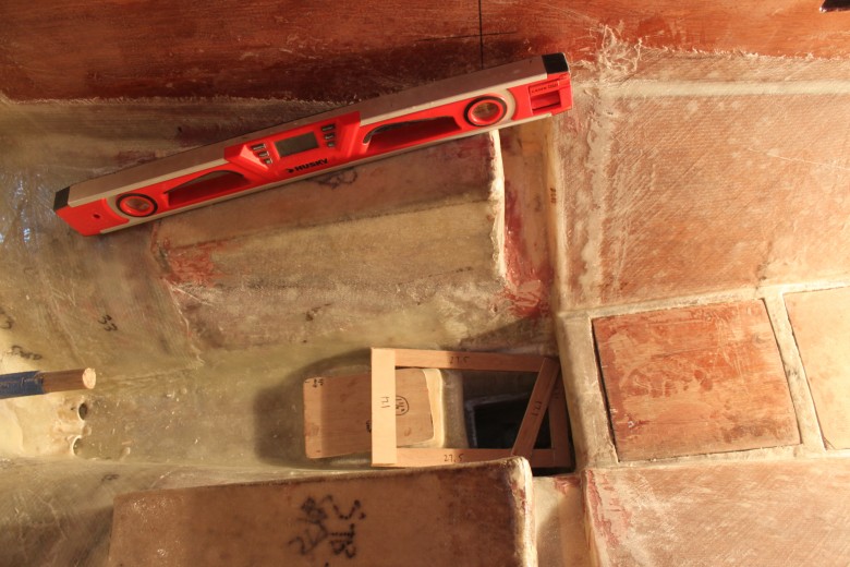
The solution I’ve come to is to add a SS pipe extension to the already “high rise” exhaust mixing elbow that is installed on my Beta 14. This will raise the exhaust mixing elbow to the required 9″ above the muffler. I would have preferred to place the muffler in a lower location, but the limitations in the engine room and below cockpit area prohibited this. For reference, here’s an image of a template of a waterlift muffler placed below the engine. It would be too tall to be placed here, because of the sump on the engine:

An image showing a template of the footprint of a water-lift muffler placed above the bilge diesel tank, and below the engine mounts. Not enough room for the muffler here!
December 29, 2011
I’ve routed 2″ exhaust hose out below the cockpit, through the lazarette bulkhead, through a lazarette “splitter” bulkhead and through the lazarette locker sole to test to see if the 2″ hose would be able to make the required bend. To do so, I had to use a 2 1/2″ hole drill and then slowly pulled the hose through the openings. Happily, I found that the exhaust line ran fine and would have the required 18″ loop above the waterline where the exhaust will exit via the transom. Here’s an image of how the loop looks in the lazarette locker:

Image showing 2″ exhaust hose looped in the lazarette locker.
Research
- Raw water that has passed through the engine or the heat exchanger is discharged by injecting it inside the exhaust pipe as close to the exhaust manifold as possible. This cools the exhaust and has the added benefit of muffling combustion noise. The cooling of a wet exhaust is so effective that rubber hose can be used to plumb the exhaust beyond the water injection point. This allows a soft-mounted engine to jump around without stressing the exhaust plumbing. (This Old Boat, p. 350)
- …a wet exhaust is easy to plumb. The only rigid part is a short section attached to the manifold that incorporates the water injection fitting. This is the mixing elbow and is supplied on most marine engines…Once water has been injected into the system, exhaust plumbing downstream may be rubber exhaust hose. (This Old Boat, p. 351)
- The standard mixing elbow can be plumbed directly to a water lift muffler with rubber exhaust hose, as long as the water injection point is at least 6″ above the waterline and the water-lift muffler can be mounted lower than the exhaust manifold. Unfortunately the location of most sailboat auxiliaries puts the mixing elbow below the waterline. If the muffler can still be located lower than the exhaust manifold, the only real accommodation you have to make is to prevent raw water from continuing to flow into the exhaust system when the engine is stopped by looping the cooling water discharge line well above the waterline and equipping it with a vent at the top. The usual installation uses an antisiphon valve, but these valves are notorious for packing up with minerals and seizing. If the valve seizes in the closed position, it will not break the siphon and the engine could fill with raw water. If it seizes while open, it is like a saltwater sprinkler going off in the engine room…Dispensing with the valve and venting the loop with a 1/4″ tube leading to an overboard vent is less trouble-prone alternative, although the overboard fitting may weep a bit. (This Old Boat, p. 351)
- On the exhaust side of the waterlift muffler, the hose must be looped at least 12″ above the waterline. In a very deep boat this can result in an excessively high lift. If the distance from the bottom of the muffler tot the top of exhaust loop is more than about 3′, engine performance will suffer due to excessive back pressure. In this case, the muffler must be mounted higher. (This Old Boat, p. 351)
Anti Siphon Valve
- A traditional rubber-flap type of siphon break tends to plug up with salt crystals. This can render the siphon break inoperable and/or cause raw-water cooling system to spray salt water over the engine and its electrical harness….better yet is to remove the valve element altogether, and instead attach a small length of hose that is vented via a through-hull into the cockpit or overboard (above the waterline at all angles of heel). This way, there is no valve to leak or plug. (Cruising Handbook, p. 206)
- From the siphon break, the cooling water injection line will drop down to an injection point into the exhaust. To keep water out of the engine, the injection point should be at least 4” below the level of the exhaust manifold. The injection nipple must point down the exhaust line, away from the manifold. (Cruising Handbook, p. 206)
Heat Exchanger
- All modern diesel engines have heat exchangers. Raw water (seawater) is pumped through one side, freshwater is circulated through the other side. The raw water is sucked out of the sea by a raw-water pump, driven through a heat exchanger, and then usually dumped into the exhaust and pushed overboard by the exhaust gases. The freshwater is recirculated through the engine, the same as cooling water on an automobile. (Cruising Handbook, p. 204)
- Fresh water circuits almost never cause trouble as long as antifreeze is added and periodically changed (every couple of years; the antifreeze has corrosion inhibitors that “wear out”) and the water-pump is kept in good condition. Raw-water circuits are another matter: they are susceptible to blockages, pump failures, and corrosion. If the raw water fails, the engine will overheat (Cruising Handbook, p. 204)
- Make sure that there is a good-sized, readily accessibly, see-through raw-water strainer. (Cruising Handbook, p. 204)
- It is very important that the seawater inlet should have a strainer system either built into the sea cock or a high level system with visual inspection glass (as shown)mounted just above the water line. The inlet sea cock should be 1” BSP to which a 7/8”/ 22 mm hose connector can be fitted. The sea water pump is 22 mm OD to suit the 22 mm ID hose. Good access to the inlet sea cock is essential so that plastic bags or seaweed trapped in the intake can be poked out. (Beta Operators Manual, p. 10)
Hose
- See ‘Hose & Fittings‘ project page
Inlet & Outlet Location
- the outlet will still be submerged much of the time during sailing. With a high loop (or manufactured gooseneck), this rarely presents a problem in terms of backflow. If you use the existing location, you should still run your high loop and gooseneck as high beneath the deck as physically possible. Under all normal circumstances, this basic setup works effectively to prevent backflow through the exhaust, even when the outlet is submerged during sailing. (http://www.plasticclassicforum.com/forum/)
- Most diesels use a 2″ ID outlet. If you need to increase the size, that’s another good reason to relocate it to a more conventional location higher in the counter. I think it’d be nice to have it high enough that people in the cockpit won’t submerge it when you’re relaxing at anchor or dockside. (http://www.plasticclassicforum.com/forum/)
- There’s no set distance that an outlet should be above the waterline. The criteria for installation found in ABYC P-1 include the basic admonition that “the exhaust system should be designed and installed to prevent cooling water, rain water, or raw water from entering the engine through the exhaust system under all normal operating conditions”. How to go about accomplishing this is something that varies from installation to installation, so there is no means of providing specific guidance in terms of height above waterline, etc. (http://www.plasticclassicforum.com/forum/)
- The exhaust system has to work well both while the boat is lying at anchor and while she is sailing at a severe angle of heel in rough weather. This means that there must be a high loop in the system to keep water from backing up into the engine, as well as a pine plug to shove into the pipe in the transom when you’re running in heavy seas. (Desirable and Undesirable Characteristics of Offshore Yachts)
- Loop in exhaust hose should rise approximately 18” above waterline. (Beta Exhaust System Manual)
- With a conventional water-lift-type exhaust system, the raw-water injection line, which runs from the heat exchanger into the exhaust, must be looped well above the waterline (at all angles of heel), and must have a siphon break installed at the top of the loop. (Cruising Handbook, p. 204)
- To avoid water being driven up the exhaust by following waves or wakes, the exhaust hose from the silencer must be looped up inside the boat well above the waterline before dropping down to the exhaust through-hull. (Cruising Handbook, p. 207)
- Transom exhaust outlets should be protected from following seas. The high loop is supposed to provide protection, but….a ball valve in the exhaust line is your best protection from this disaster, but you must remember to close it (and open it!)…it is usually difficult to make access to this valve convenient. (This Old Boat, p. 352)
- A flap at the exhaust outlet is less trouble [than a ball valve], but might prove ineffective, depending on the angle at which your discharge exits the hull. (This Old Boat, p. 352)
- Check that the raw-water inlet remains under water at all angles of heel (Cruising Handbook, p. 204)
Waterlift Muffler
- If you have space, the fiberglass Vernalift waterlift mufflers are a nice choice. They’re bulky, though, particularly in 2″ size.The plastic Vetus ones are fine, but they can melt if for some reason the cooling water flow is stopped. But they are small and versatile, and inexpensive, so they often fit the bill. (http://www.plasticclassicforum.com/forum/)
- I should add, in case it’s not clear, that I have no personal problem with the Vetus units. I have one, I’ve installed others. But in each case, I chose it simply because it fit in a tight space where others would not.Given my druthers, I’d choose the fiberglass versions every time. Realities don’t always allow it. (http://www.plasticclassicforum.com/forum/)
- How far below the engine exhaust outlet is your muffler? It should be well below the exhaust outlet and/or riser, if equipped. It’s this vertical distance directly downstream of the engine outlet that provides that backflow protection when you stop the engine, on top of the volume of the muffler, etc.In other words, the exhaust hose should be able to drop a certain distance between the engine outlet and the top of the muffler; sometimes this is accomplished with the positioning of the muffler (i.e. well beneath the engine), and sometimes you need a high riser/loop to accomplish this. It all depends on where your muffler is located relative to the engine outlet.The high loop at the transom discharge is to help prevent backflow of outside water into the system through the final transom exhaust outlet, not to limit how much exhaust water might flow backwards when the engine is shut down. Two different height differentials, two different functions. (http://www.plasticclassicforum.com/forum/)
- The minimum size of waterlock needed can be calculated based on the volume of water your exhaust hose could hold (that hose being between the waterlock and your boat’s transom or where ever the exhaust exits the boat. The concept is that if that hose were completely filled with seawater which all drained into your waterlock, none of it would back up into the engine. Then, when sizing, add a bit of size for “insurance” measure. So, multiply the inside diameter of the hose by itself/4 and then multiply by pi (that is diameter x diameter/4 x 3.1415) and then multiply that number by the length of the hose. Work in inches for length of hose and for diameter so you’ll end up with cubic inches needed. Then, you can look at the size of various waterlocks to make sure they are larger than your minimum needed. (http://www.cruiserlog.com/forums/)
- Vetus Waterlift Muffler – 51.5W x 36.2H…The internal volume of the Vetus is around 800 cubic inches…The upper and lower half can be swiveled so the that inlet and outlet pipes can be pointing in any direction. The pipes can also be swiveled to suit most configurations. (http://www.cruiserlog.com/forums/)
- Vetus makes some great waterlifts, certain models have inlet and outlet that pivots for the exact position needed. Think Corrosion with metallic water lifts. Not much heat left in gases by the time it hits the waterlift due to raw water injection, of course if you run the engine with the raw water seacock closed you will blow out your impeller in short order (less than a minute) the temp alarm will sound at 210 degrees, still not enough time for the water lift to melt down by the time you shut down the engine wondering what the! I have held onto the exhaust hose just down stream of the exhaust elbow after running engine 32 hours straight. It’s warm is about all. (Ben Thomas, Beta Marine)
- If you are using a plastic waterlock mufflers or a fiberglass one, then we suggest a 12” length of hose between the exit of the exhaust elbow and the entry point of the waterlift muffler. This allows enough time for the water in the exhaust system to cool the gases down so you do not have any muffler problems. (Beta Exhaust System Manual)
- The waterlift is simply an enclosed pot with inlet and discharge hoses. Engine cooling water is injected into the exhaust line near the manifold, gradually filling the pot. Exhaust pressure builds in the pot as it is filled with cooling water until the pressure in the pot is sufficient to blow water and exhaust gases out the discharge port. Since the exhaust gases do not travel straight from the manifold to the outside of the boat,much of the engine exhaust noise is absorbed in the waterlift, resulting in quieter exhaust. The exhaust of boats with water lift systems is usually easily recognized by the fact that the cooling water does not spurt out the exhaust in a continuous stream unless the engine is running at high speed. Rather, water is discharged in bursts, much like the flow through a diaphragm bilge pump
- The waterlift muffler is important; it should be mounted as low as possible to the rear of the engine so that when the engine is turned off, water in the hose extending from the muffler to the exhaust tube on the transom does not exceed the capacity of the muffler and thus enter the engine. Measure their respective capacities to be sure – an inline valve is smart insurance. With our without a valve, the hose should be looped as high as possible to the underside of the deck before coming down and fastening to the exhaust tube. An additional “silencer” further quiets the exhaust. (Upgrading the Cruising Sailboat, p. 144)
- From the injection point, the exhaust should drop another 8” or more into a water-lift-type silencer. Here the water gathers at the base of a cylinder until it blocks the exhaust discharge pipe, at which time the exhaust gas pressure drives the water up and out of the final section of the exhaust. (Cruising Handbook, p. 206)
- The water chamber in the silencer must have a volume at least as great as the volume of the upward-sloping section of the exhaust hose leaving the silencer. Then, when the engine is shut down, even if the exhaust is full of water and even if it all drains back into the silencer, it will still not back-flood the engine. (Cruising Handbook, p. 206)
- Water-lift silencers are best made of fire-resistant fiberglass or plastic…many plastic water-lift silencers (including the popular Vetus silencers) melt down if the cooling-water flow is lost for any length of time. There should be (but rarely is) an alarm that signals loss of flow – either a flow meter in the water circuit or a temperature probe in the exhaust. (Cruising Handbook, p. 207)
- …require hose connections to be double clamped using all 300-series stainless steel hose clamps. Better yet for clamping an exhaust is a T-bolt clamp, but it needs a stainless steel fastener (rather than carbon steel) (Cruising Handbook, p. 207)
- Sailboat engines are invariable mounted near or below waterline, placing the discharge outlet above the exhaust manifold. If you plumbed the exhaust directly to the an outlet fitting, water in the exhaust hose when the engine is shut down would drain back into the manifold and into the cylinders with disastrous consequences. The solution to this is a canister plumbed into the exhaust and located below the manifold to serve as a sump for water still in the hose. However, if the canister is just a hollow tank with an inlet and an outlet at the top accumulating cooling water will soon fill it and water draining back from the downstream hose will overflow it back into the engine, so our canister has a simple but ingenious design feature. The outlet pipe extends into the interior of the canister almost to the bottom. Now the injected water accumulates in the canister only until it covers the bottom of the pipe where it blocks the outlet. When sufficient exhaust pressure builds up in the canister, the water and exhaust gases are literally blown out of the submerged outlet pipe, so the canister remains mostly empty. This canister is known as a water-lift (or waterlock) muffler. (This Old Boat, p. 350)
- …be certain your waterlift muffler is firmly attached to the boat. Do not be fooled by the light weight of an empty plastic muffler. (Plastic mufflers work perfectly, by the way, despite the seeming incongruity). When partially filled with seawater, the muffler will have considerable momentum in a pitching or rolling boat. (This Old Boat, p. 351)
- ….avoid mounting the muffler to one side of the engine. This is particularly important for sailboats, because a side mounted muffler will be elevated relative to the exhaust manifold on one tack. At large angles of heel, residual water in the muffler could flow into the engine. Try to mount the muffler close to the fore-and-aft centerline of the exhaust manifold. (This Old Boat, p. 352)
Image Gallery


Comment Form