Tankage
Project Logs
September 24, 2011
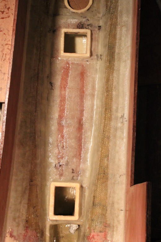
The sump tank construction is fully complete. The valves have been installed which will allow the 3 forward areas of the boat to be individually sealed off from the rest of the boat. Access to these valves will be quite tight. If I had to do it again, I would have likely increased the access to these, though in truth, I would only be able to give a few extra cm of clearance, due to cabin sole head height requirements. To help with being able to open and close the valves, I’ve drilled holes into the PVC valves so I can attach small chains to pull the valves close, without needing to have my whole hand in the sump tank.
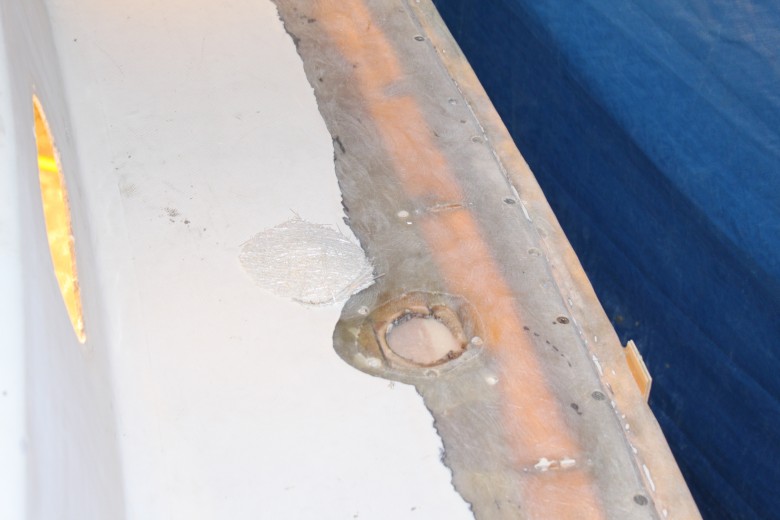
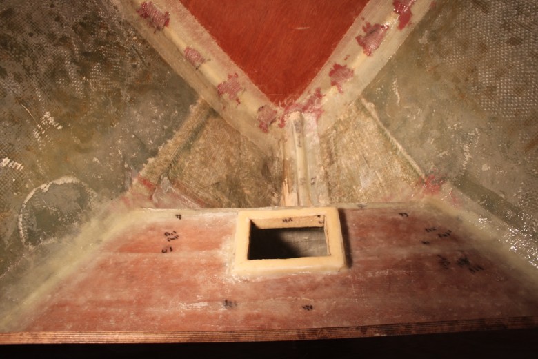
The tank lid has also been test fit and just needs to be installed firmly in place. The lid I used was an access lid, which I’ve often seen installed on the deck of boats, but will work well for the sump tank as there isn’t any need for the tank to hold liquid. Here’s an image of the sump tank as it is now:

This image shows the sump tank with the round opening with the forward diesel inspection port aft of the sump opening.
August 11, 2011
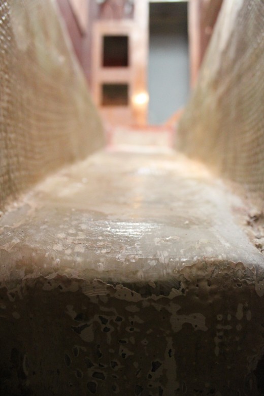
The sump tank is now essentially complete. The plastic access hatch I purchased has been test fit and I can confirm that it fits the sump tank access port. All the valves and PVC drains are installed and in place. The area around the opening to the sump drain has been faired.
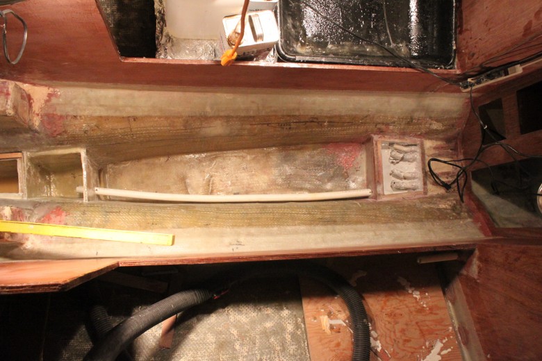
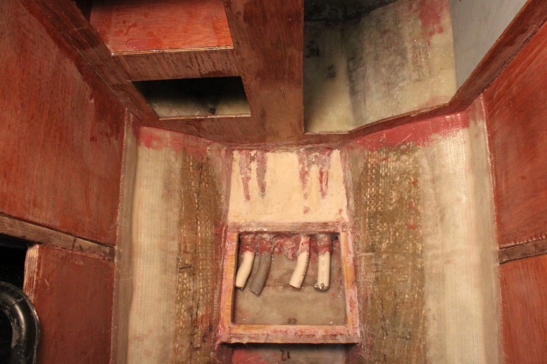
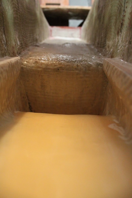
If it wasn’t already clear, the sump tank is a small area that collects water from the forward-most water-tight compartments. The sump drains into the bilge via a 1″ PVC drain and can be shut off with a PVC valve. Inside the sump are 3 PVC valves which I can use to shut off the forward-most water-tight lockers. This means that I am able to completely seal the forward area of the boat by managing the valves in the sump area. Here’s an image of the PVC pipes as they run into the sump:

This image shows the PVC pipes in place. Their outlets are in the sump tank and each pipe connects to a different locker compartment.
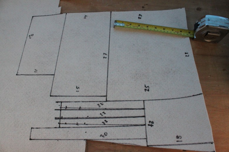
I’ve also been working on the diesel tank lids. I am making templates for the eventual stainless steel pieces which will create a lid. The diesel tank has 3 access ports overall, and each lid is a custom fit. As Tomahawk Boatyard has a welder in the yard (Leonard), I’m going to work with him to get some aluminum lids created. The lids will have the fittings welded to them and will likely be made of aluminum.
August 2, 2011
I added a couple images of how the cabin sole has affected the lid access to the diesel tanks. Basically, the cabin sole will be built all around the lids. The reason for this is that I poured foam above the tanks to support the cabin sole and construct a drip pan.
I should also mention that I added images of the original gas tank that was in place when I purchased by Bristol sailboat. I believe it was made of monel and was in good condition. As I had no plans to use the tank, I ended up selling the tank on Craigslist for $75 (with strong urges to the next owner to verify it didn’t have any leaks; he was a mechanic).
As far as future gasoline tankage, at this time, I have no plans to use gasoline on my boat. I may need gasoline to power a generator eventually, but my plan is just to use jerry cans. I may end up stowing the jerry cans in the lazarette sea chest/chain locker (to be added later), though I’m not 100% sure on how well ventilated this area will be, thus giving me some concern as to the ability to safely stow jerry cans of gasoline in this area. Likely, I will do more research on this as I build the Lazarette locker, so I would check there for future information.
July 25, 2011
As I’ve been working on the cabin sole, I realized I needed to lower the middle diesel tank flange. This meant that the extra high flange I had built previously had to be cut down. It did represent a fair amount of wasted effort, but that’s just how things go and I was never 100% sure about the flange height while building it anyway.
The reason I had the tank flange higher was due to the tank’s design. Since the tank is built in two separate compartments with one compartment being slightly higher than the other, I had built the flange higher to accomodate the elevation difference. This would mean that if I filled the tank to it’s heighest fill level, the liquid inside wouldn’t be resting agains the lid. This would allow me (if I wanted) to fill the tanks with an extra liter or so without the liquid pushing against the lids. (I hope that makes sense, but the photos may explain more and if I you have any questions or need for clarifation, leave your question in the comments section below)
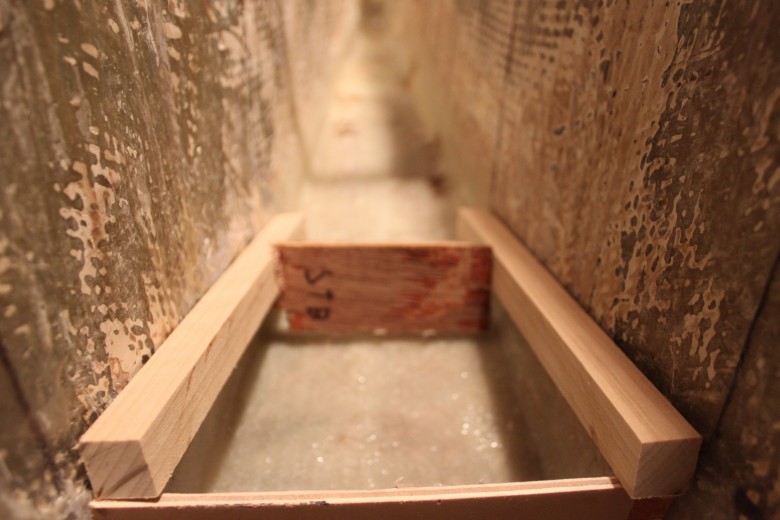
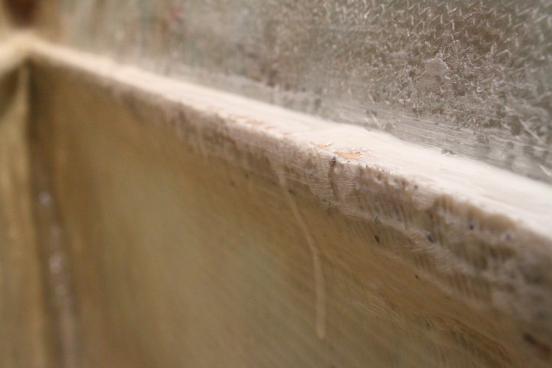
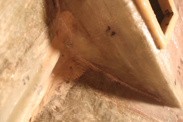
The other reason I built the mid flange higher than the others was due to the fact that the sole between the nav-station and galley would be quite a bit higher than the normal sole. As it turned out, the raised sole would be noticeable lower, which meant less room below the sole and less room for fittings if I had a raised flange. I want it lower. Here’s an image of the diesel tank lid flange in discussion:

This image shows the two aft-most diesel tank flanges. The forward of the two had to be trimmed down so the cabin sole height could be reduced.
Today also marks completion of major construction of the diesel tank. Last weekend I installed the lid onto flanges that I had built. Here’s the basic steps for how the installation of the lid was done:
- 2 layers of 6 oz fiberglass cloth were epoxied to the underside of the lid, then coated with 7 coats of resin rich epoxy. After the resin was all laid on the underside of the lid, the lid was heated for a high post-cure temperature.
- After doing some minor repairs to the underside of the flange, the lid had a final fit and I cut all the glass for the installation.
- Once everything was ready, I wetted out some Baletk mat, placed it on the pre-constructed lid flange and then placed the lid onto this.
- I weighed down the lid with cinder blocks and while the weights were in place, I poured unthickened epoxy into the area between the lid and the hull, effectively filling any possible voids between the hull and the baltek.
- Once the baltek had kicked, I removed the weights and wet out the top of the lid in the areas that would receive glass (the entire thing).
- With the unthickened epoxy warming up, thickened epoxy was also placed in all same seams as the unthickened epoxy.
- A thin strip of 1708 biaxial cloth was pushed into the thickened epoxy.
- 4″ strips of 1708 biaxial cloth were applied to all seams.
- 6″ strips of 1708 biaxial cloth were applied to all seams as well as to all areas on top of the tank
- With everything kicking, I reached into the tank and coated the Baletk mat with 4 coats of resin rich epoxy, then left the tank to cure at a higher temperature using a shop light stuck inside the tank.
Once the lid was installed, I did some fine tuning of the lid flange to ensure it was a flush fit for the eventual meta lid. I just templated the lids for all the tanks I made and I will be giving those to the local welder soon so he can begin fabrication.
July 14, 2011
I’ve been working on the diesel tank for a week or more and so far, it’s been one of the most involved projects to date. Building a fuel tank of any kind requires a lot of careful fiberglass and epoxy work as well as careful planning of each step, because once the tank is in, there’s no chance to go back and make changes.
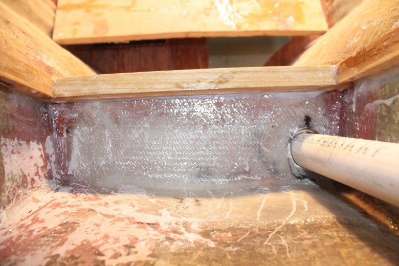
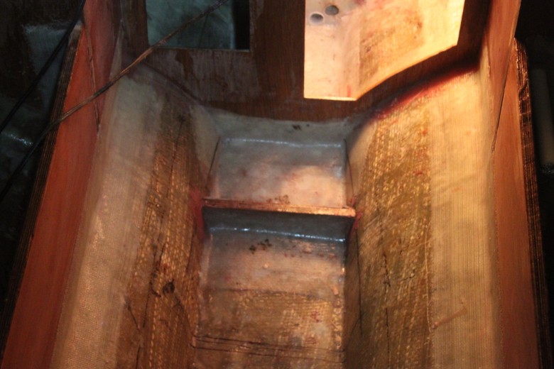
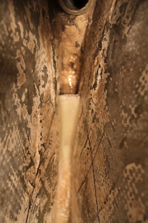
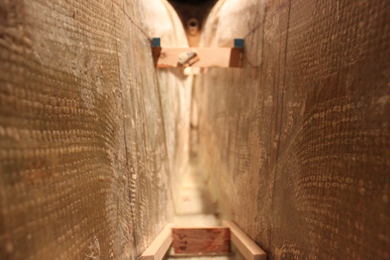
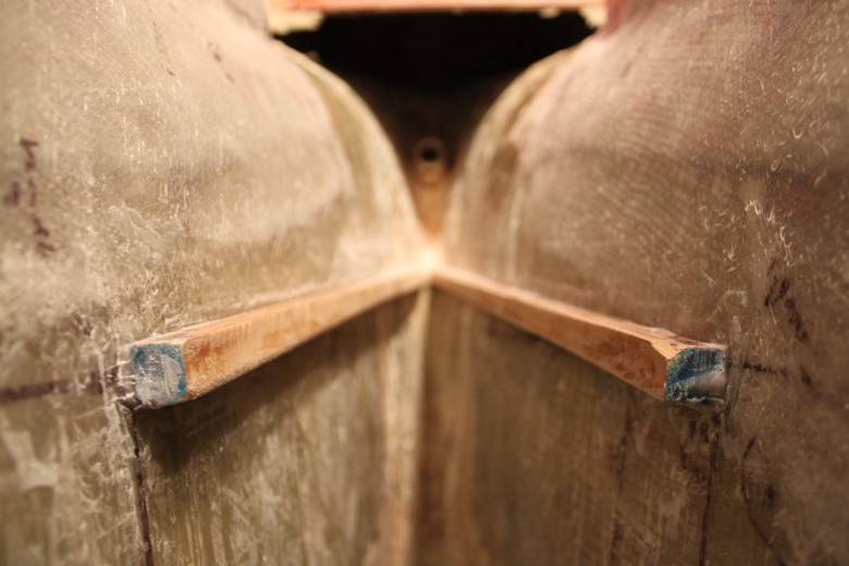
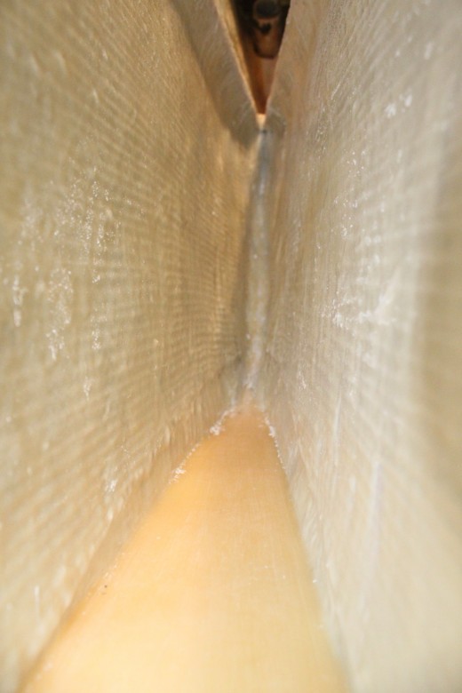
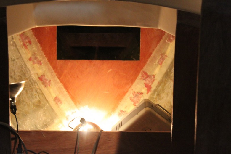
I made a big design change just prior to installing the tank. That decision was to build the tank in two different sections which are connected via a channel. The channel is below the new bilge area and overall, the design increased my diesel tankage by over 10 gallons. An image is probably are the best way to describe the channel:

This image shows the area I decided to convert to the diesel tank. The forward two flanges are the bottom of the soon-to-be-created bilge. Note the small gap below the bilge sole; this allows fuel to flow to the forward portion of the diesel tank.
June 24, 2011
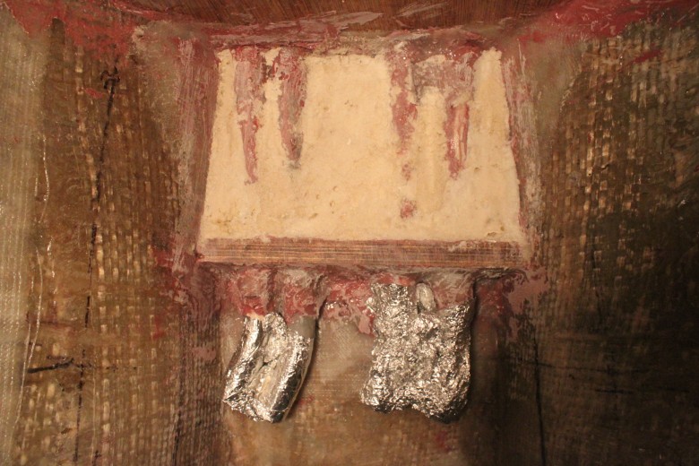
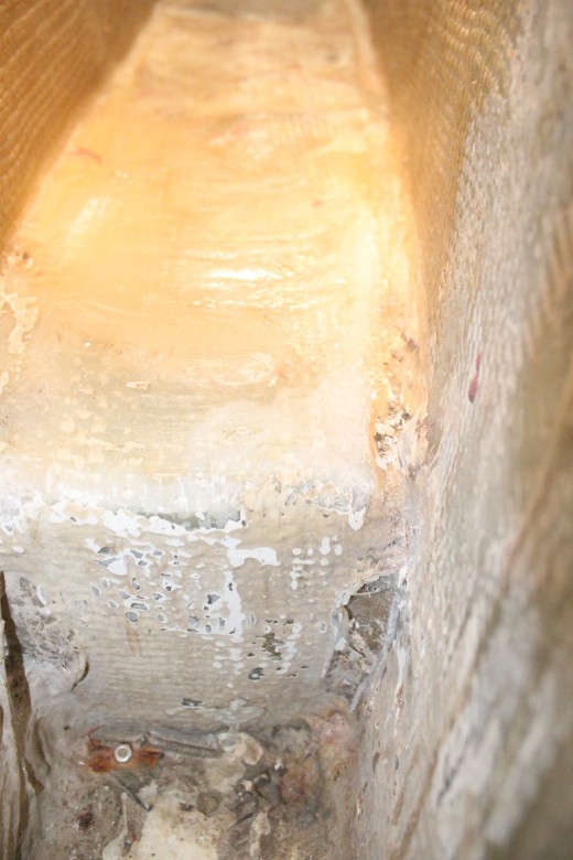
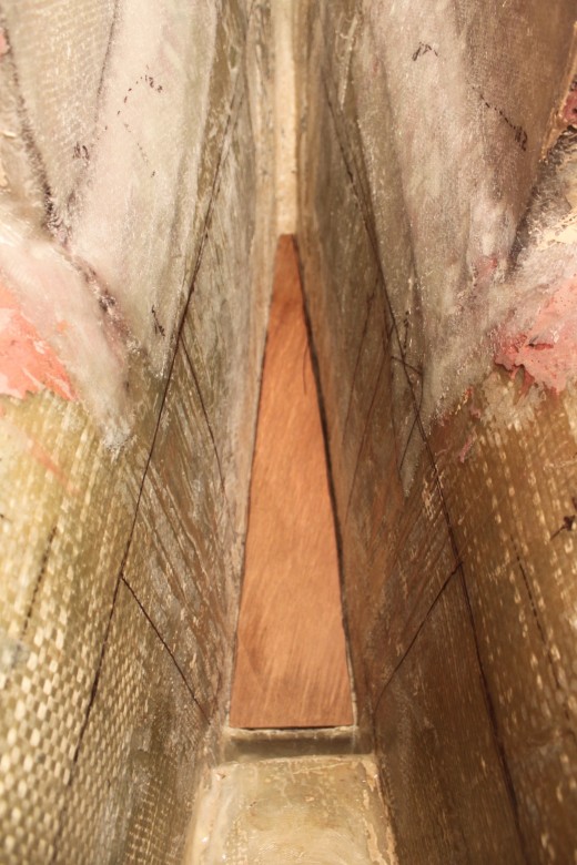
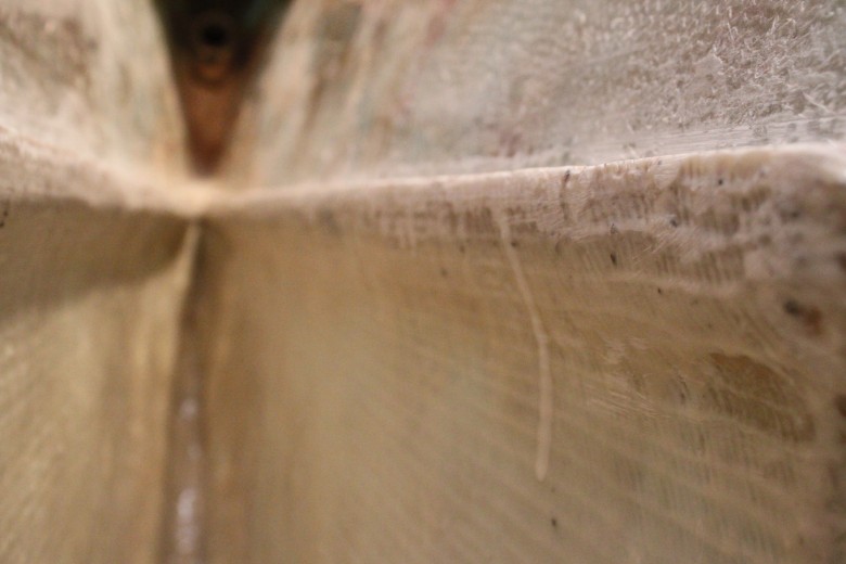
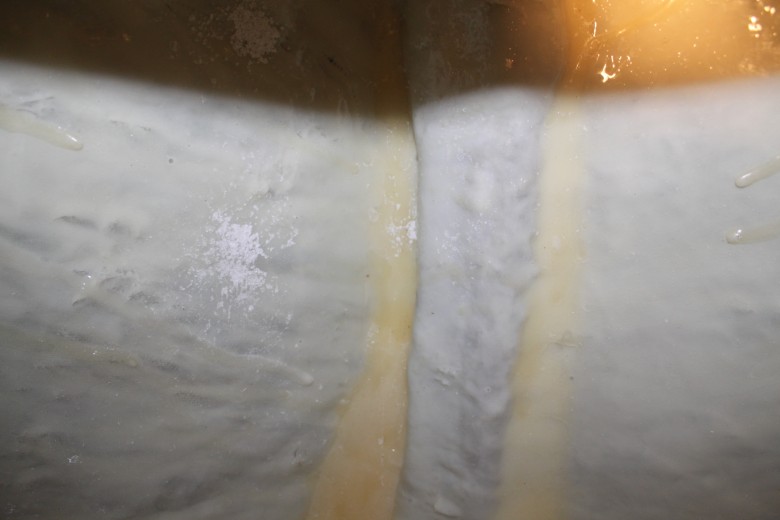
I’ve installed the tank and the PVC lines that will drain into the sump. I’ve also created a sump tank lid using some old fiberglass I had from the original fiberglass water tank. Overall the sump proved to be a simple installation, however there was key measurement to remember: cabin sole position. The sump’s height dictated where the final sole’s height could be above the sump. Here’s an image of the sump tank lid before I installed it on the sump’s lid flanges:

This image shows the odd shape of the sump tank lid. The rough epoxy is the beginning of the lid flange for the sump tank.
I’m not exactly sure when I’ll get around to the final construction of the kerosene tank, but I’ve installed the forward bulkhead of the tank already. The reason for this is because I needed to run two PVC pipes for the chain locker and forward-of-kerosene-tank locker. I also installed a PVC tube that goes through the head which, eventually, will allow a kerosene line to run down to the heater without compromising my water-tight compartments.
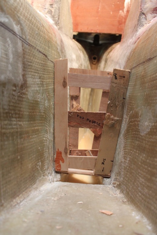
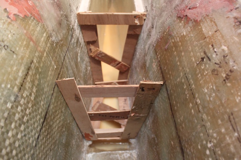
The tank wall installation was just your basic template, cut, and fiberglass job. I decided to go with a 3/4″ piece of plywood for the tank wall, not because it was necessary for the kerosene, but because this was a forward location in the boat that I felt could use a bit of stiffening up in an area that will be constantly crashing into waves. Here’s an image of the new forward tank bulkhead I added to create the sides of the kerosene tank:

This image shows the forward kerosene tank bulkhead supported so it can be epoxied in place. Once hard, the thickened epoxy holds the piece firm, allowing for easier fiberglassing.
Research
Diesel Tank
- A key concern is that the engine must have clean fuel. Since fuel tanks collect sediement, many yachts have experienced fuel problems in rough weather, when sloshing about stirs up dirt. Of course, tanks should be cleaned periodically and before long passages… ( Desirable and Undesirable Characteristics of Offshore Yachts )
- Fuel tanks should vent overboard so diesel fumes or over filling fuel will not foul the interior of the boat. ( From a Bare Hull, p. 280 )
- To have fuel tanks near the engine is good. The shorter the fuel lines the better. ( From a Bare Hull, p. 164 )
- There is a great image of a fuel tank and all it’s pieces – IMAG1366.jpg (In “Plumbing” photo folder)
- Naval architect Roger Marshall suggest that fuel tankage hold an amount equal to three or four percent of total displacement. (Upgrading the Cruising Sailboat, p. 148)
Greywater Tank
- When considering where to locate grey water tanks, we recommend making a model of the tank using cardboard and tape. It makes it easier to appreciate the tank size and shape, and where inlets, outlets, vents and hatches, level sensors etc, are to be located on the tank, it also helps you to consider where pipework will run throughout the boat and whether the tank, once made, will pass through the boat to the intended location. (http://www.boatwide.es/english/blackandgrey.htm)
- From galley sinks there may be food waste and other waste from showers. A typical installation would be to have all pipework from all sinks and showers to go via multiple inlets into one tank which also has an outlet, vent and a maintenance hatch (http://www.boatwide.es/english/blackandgrey.htm)
- An optional pre-tank filter box is also available for a more robust system solution. (http://www.boatwide.es/english/blackandgrey.htm)
- I was also thinking about having a trap under the galley sink as well – as it is directly above the sump, so the smells don’t go directly up…Its possible to have a single trap before the sump that takes all them if you have the room and access for maint. (http://www.cruisersforum.com/forums/f115/grey-water-sumps-pumps-and-johnson-ultima-float-switches-24760.html)
- The grey water tank has to drain COMPLETELY so that the extra water cannot innoculate the next batch of water. (http://www.oasisdesign.net/greywater/misinfo/index.htm)
- There are two holding tanks. One for the forward head and the other for the aft. The discharge from each tank is plumbed to the Y valve on the right. The Y valves are Whales with a center off position. The valve on the left selects either the Jabsco diaphragm waste pump or the deck pump. The hose is Trident 101. I may regret not taking Peggy Halls advice and using the SeaLand hose but I couldn’t find any discounts on it.101 hose is a bear to work with. Regular 1 1/2″ hose fittings don’t work. Shields makes special fittings that work well with a little help of a smear of KY. (http://www.rutuonline.com/)
- Here are some pro’s for having a greywater tank (http://www.cruisersforum.com/forums/f115/chain-locker-drain-into-greywater-tank-24648.html):
- In some protected areas, no water is allowed overboard, so a grey water tank is necessary to store the drainage until you are out of protected waters.
- Also, less thru-hulls
- Here are some con’s for having a greywater tank (http://www.cruisersforum.com/forums/f115/chain-locker-drain-into-greywater-tank-24648.html):
- Silt or gunk draining off the chain and eventually either stinking up your tank, or filling it up.
- And, in a heavy sea, water draining into the anchor locker might keep filling that tank–until it overflows and goes where? I know I’ going to be tossing nasty stuff down the sink…right? If so, that is bad to go inside the boat somewhere, THEN out.
- There may be bacterial growth from a buildup of food particles and grease.
- Suspended solids.
- A gray water tank is full of bacteria, and can stink as bad as, even worse than, a waste holding tank.
- Plus, gray water tanks also have grease, soap scum, hair etc to deal with. Your galley and head sinks can drain directly overboard…only the shower needs a sump. And a small sump is a LOT easier to keep clean and odor free than a tank.
- James says – When I installed my greywater main run from my forward head to the tank, I left an opening at the forward most end of the line to allow me to tie in a drain line from the chain locker (with p-trap)The reason I did this is the only water I get in the bilge forward of the packing gland is from the wet chain. It travels all the way back to my sump under the engine. I figured if I could install a drain just a bit off the bottom of the chain locker I could save a lot of mess in the bilge. I have a nice slope and everything seems to work out well for this. Grey water does smell so its not suitable for flushing for me. All the sinks and showers gravity drain into the grey water tank.The idea was to install the drain in the chain locker on the side, just above the floor so I could muck out the mud or grass before it gets into the tank.I will put a valve on the drain for heavy seas…Later, some posters suggested a drain in the anchor locker, but James wasn’t sure if the locker floor level was high enough above the waterline to do so….Some posters were confused why James would want to do this, James’ reasons were – Its a place for the sink and shower drain water to live until I can get out to sea and dump it. No discharge areas are getting more and more common.Some of the most pristine gunk holing around here is in Turkey…some of those areas are very strict.Since I’m doing a major refit I thought it prudent to try and set the boat up in a way that would comply. Another poster replies – We have a gray water tank too and like it. Every drain in the boat is like in a home and gravity fed into the GW tank which is inside the keel.But I don’t like draining the chain locker in the GW tank because you open a path from the sea into the boat interior. I think this is to be avoided (http://www.cruisersforum.com/forums/f115/chain-locker-drain-into-greywater-tank-24648.html)
Inspection Port & Lids
- Any future maintenance on the tank (like cleaning) will have to be done via the 6 inch inspection port mounted on the top near the aft edge. As long as 9 inches is kept clear aft of the tank, the hold down bracket can be unbolted and the tank slid out to reveal the inspection port. Should something foul the tank beyond use in the future, that cant be fixed via the inspection port, it will need to be abandoned in place, until fuel tanks and/or engine come out (hopefully never). (http://www.westsail42.com/2008/12/grey-water-tank-is-in.html)
- Whatever a tank is made of, it ideally should have inspection ports large enough to permit cleaning when necessary. There should also be easily accessed aperture through which the tank can be sounded with a rod, as mechanical and electrical gauges are often unreliable. (The Modern Cruising Sailboat, p. 256 – 7)
- All tanks need inspection hatches large enough to accommodate getting inside to clean out the interior (Cruising Handbook, p. 216)
Kerosene Tank
- In traditional kerosene and alcohol stoves the liquid fuel is first pressurized inside its storage tank so that it flows smoothly to the burner when the burner is opened. The tanks are relatively small, mounted either remotely or integrally. Little pressure is required, about 20 – 30 psi which is created with a small manual piston pump. Some cruisers use Schrader tire valves on their tanks and use a small bike pup instead. Before it is lit, a burner must be preheated so that the liquid fuel vaporizes as it flows out the burner’s jets. ( The Modern Cruising Sailboat, p. 266 – 7 )
- A permanent gravity feed system…can be filled through the same sort of deck fill used for water and engine fuel – just be certain the fill is labeled correctly. A tank vent tube is necessary and tis may be routed through the deck or inside of the cabin. ( Upgrading the Cruising Sailboat, p. 285 )
- (For images of gravity fed kerosene tanks, see Fig. 14-3 & 4 from Upgrading the Cruising Sailboat, p. 285)
- The tank end of the outlet pipe inside the fiberglass or stainless steel tank should protrude up an inch from the bottom so that sediment doesn’t reach the stove and heater burners. Otherwise, install a filter in the system. ( Upgrading the Cruising Sailboat, p. 286 )
- A couple living aboard in a warm climate might expect to use about 1 gal. of kerosene each week for the stove/oven and cabin lamps. A 30-day supply could be contained in a five-gallon gravity feed tank, obviously a larger main tank…with a 20 – 30 gal. capacity, would give several months of fuel, though less in colder climates with a heater running. ( Upgrading the Cruising Sailboat, p. 286 )
- Each tank should have a positive action valve, such as an in-line vall-valve. it’s also handy to have a tap for filling lamps (use rigid tubing, not nylon); this is much less messy than pouring kerosene from a portable tank. ( Upgrading the Cruising Sailboat, p. 286 )
- To make oil lamps convenient, a gravity fill tank is imperative. Chasing a funnel and a 1-gallon can around the cabin sole will frazzle even the toughest sailor. Fit copper tubing from the tank to a tap mounted in a convenient spot in the cabin. Then you can fill lamps with ease and no spillage, especially if you remember to do it before dark. We have found that this instant tap of kerosense has many uses: cleaning grease off our teak topsides, cleaning brushes, thinning paint and varnish. ( The Self-Sufficient Sailor, p. 190 – 1 )
- Our gravity tanks holds 8 gallons of fuel so including paint clean-up at haul-out time, our tank holds a six month supply. ( The Self-Sufficient Sailor, p. 192 )
Securing, Support & Placement
- The stainless steel ones [strap] can be adjusted by using a split strap system with a piece of all-thread (a stainless steel rod threaded from end to end) as a connector. (From a Bare Hull, p. 282)
- I strongly recommend against using the quick release type for this may release the tank at the least desirable moment. The old fashioned friction buckle system seems to work well. (From a Bare Hull, p. 282)
- All tanks must be securely fastened to the hull and insides of furniture to keep them from moving around and possibly cracking open. Two methods are two glass strips of wood to the hull, or glass or bolt blocks of wood to the inside of furniture. Flat steel straps also can be run around the tank to hold it up in place, using turnbuckles to tension the strap. (Upgrading the Cruising Sailboat, p. 90)
- Whatever the type, any metal tank should be shaped and installed so as to minimize the contact with moisture and standing water. The tank should be separated form any mounting surfaces by nonabrasive, non-absorbent materials such as high-density plastic or neoprene, should be configured to shed wear when the boat is idle and should not be located anywhere bilge water is apt to collect and stagnate. (The Modern Cruising Sailboat, p. 256 – 7)
- A 60-gallon tank full of water weighs 500 lbs. Depending on the tank’s location, it will develop considerable G-forces when the boat is pounding, constantly working away at its mounting brackets. Too many tanks rely primarily on gravity to stay in place – if the boat gets knocked down, there is a serious risk of the tank coming loose. (Cruising Handbook, p. 216)
- In terms of support and weight distribution, is is best if a tank is completely integral, custom shaped to fit into the space it inhabits and positioned as low in the boat as possible. (The Modern Cruising Sailboat, p. 256 – 7)
- Not only will this positioning make for a stiffer boat, but the area of least movement in the boat is down and low and near the centerline. Even in the most disorganized seas, the tanks in this location will have fewer forces working on them, thereby increasing their life expectancy. (From a Bare Hull, p. 164)
- …it’s not difficult to see that a large tank will be holding several hundred pounds of water and that its placement in the boat can be critical to trim….try to locate fuel and water tanks as close as possible to the boat’s center of gravity to prevent hobbyhorsing….with a deep enough bilge, this is an ideal location. Bilges are near the center of the boat, handy, yet out of the way. Two other probably locations in many boats are beneath the v-berth, beneath settees, or on boats without quarter berths, just behind the bulkhead that separates the cabin from the under-cockpit area. Anytime tanks must be located to either side of the centerline, two tanks are necessary to counter one another (unless you can compensate for excess trim in some other way) (Upgrading the Cruising Sailboat, p. 89)
- An integral tank forward is often praised as also serving as a watertight compartment in the event of holing the bow. Maybe, but if you hit something hard enough to punch a hole in the hull, I wouldn’t count too heavily on a tabbed bulkhead to remain attached. (This Old Boat, p. 329)
- …putting 300 or 400 pounds of water (at about 8.34 pounds per gallon) in a tank of any types that’s high up in the eyes of the boat is a bad idea from a boat performance standpoint. Extra tankage ideally should be located low and near the center of the boat (This Old Boat, p. 329)
- …never forget that the very first measurement you must take is the size of the companionway opening. (This Old Boat, p. 329)
- No section of tank should contain more than 20 gallons without a baffle. If more is allowed, a half-full tank in a violent sea can throw about great amounts of liquid of not little weight, putting unnecessary strain on seams and fastening. (From a Bare Hull, p. 166)
- Large tanks should have baffles to prevent contents from sloshing around too much, as this may threaten the tanks structural integrity, creates unwanted noise and can affect a boat’s performance in a seaway. (The Modern Cruising Sailboat, p. 256 – 7)
- …if there are baffles, it should be possible to stick a hose under them to flush out all sections. (Cruising Handbook, p. 216)
Rainwater Catchment
- Let the rain run off the decks for a few minutes to clean them of salt & dirt, then put plugs in all the scuppers and opened a couple of ports (one on each side) that led into the water tanks. Once the tanks fill up, if it rains that long, close up the ports, and reopen the scuppers. (http://www.cruisersforum.com/forums/f91/catching-rainwater-43495.html)
- Rain + nonskid to do laundry. (http://www.cruisersforum.com/forums/f91/catching-rainwater-43495.html)
- In a good Tropical downpour we can fill two x 200 litre tanks in around 10-15 minutes. (http://www.cruisersforum.com/forums/f91/catching-rainwater-43495.html)
- I would add that we do not use any chemical cleaners on the deck, it’s teak, except before a passage when we clean the whole deck carefully with clean water and a sponge, maybe a little washing up liquid if it’s particularly dirty. (http://www.cruisersforum.com/forums/f91/catching-rainwater-43495.html)
- We sewed sunbrella ‘gutters’ on the bimini which deflected the water to the front corners, but a 6’x6′ piece of canvas will collect enough water to fill the tanks in the tropical deluges. We tended to collect at anchor more than on passages. (http://www.cruisersforum.com/forums/f91/catching-rainwater-43495.html)
- It was simple, required a few rags or towels to act as dams and diverters, and worked well when the winds piped up. I had a 3″ caprail and that made it easier than caprails with the aluminum railing. I also found that by using a towel as a diverter to move the wide deck torrent towards the deck fill really helped. (http://www.cruisersforum.com/forums/f91/catching-rainwater-43495.html)
- Depending on the amount of rain, sailing conditions, and other factors, it may take 10-15 minutes to get the water clear enough to put in the tank. I’ve found that a good filter and some common sense seemed to work best. Rain water is quite clean and after getting the decks clean, quite sweet. If you’re in a metropolitan location, you may have to wait longer for the rain to wash the air clear and get the deck clean. (http://www.cruisersforum.com/forums/f91/catching-rainwater-43495.html)
- The biggest problems I’ve had with getting water was from shoreside places. Some of the water sources clearly weren’t as pure as waiting on the rain. In that case I put the jerry jugs through a basic filter (spun particulate and carbon) and added a 1/4 cup of bleach to the tank. (http://www.cruisersforum.com/forums/f91/catching-rainwater-43495.html)
- The idea is that you catch good clean rainwater, so not in area’s with air pollution or when a tropical wave brought Sahara dust to the Caribbean or similar situations. In the Caribbean we look for rain from ITCZ squalls. The water coming down is pure to 20ppm on my meter, which is very good. (http://www.cruisersforum.com/forums/f91/using-sea-water-in-the-galley-35700-3.html)
- The question is how to keep it clean in the process of catching it. This is different for everyone because the technique to catch it is different. We use almost all of the decks to catch it, so we must assume they are not clean enough. The really bad spots like around the windlass isn’t used, plus we have awnings to help bring the rain from the center of the boat to the side decks. The awnings and side decks must be clean (http://www.cruisersforum.com/forums/f91/using-sea-water-in-the-galley-35700-3.html)
- When I wrote that I caught 400 gallons, I should also have mentioned that during those 20 minutes, I lost at least another 200 gallons because my two 1.5″ diameter deck fills could not handle that much water in so little time, spilling at least a third over the 2″ high toe-rail. (http://www.cruisersforum.com/forums/f91/using-sea-water-in-the-galley-35700-3.html)
- …we would remove any gas or oil jugs or similar material from our decks upstream of the fill pipes, let the rain wash the decks thoroughly, plug the scuppers with clay, and let water pour rain into the tanks…If we expected rain we would wash the decks with Joy and sea water. Then the rain would have to wash off only the salt before we could open the tanks…Other folks catch water in their bimini tops by running hose from drain holes in the corners to the tanks. Others use awnings. These types of catchments, as neat as they might look in a book, seldom work well because when it’s raining, it’s usually blowing; they dump the water no matter how hard you try to tie them down…You can very quickly construct temporary dams with strick of wood and modeling clay to funnel the water to fill a hole. (All in the Same Boat, p. 174)
- One advantage of deck fills it that a rain-water catchment system can be routed directly through them into the tank. Filling buckets adds an extra step. Whenever filling a tank through a deck fill, it should be your routine practice to wash down the deck around the deck fill before opening the cap. (Upgrading the Cruising Sailboat, p. 94)
- The rain itself is none too clean, either. Dust, soot, salt, bacteria and other invisible contaminates can be found in collected rain water. For this reason, a catchment system should incorporate a filter between the deck fill and tank. As a furhter precaution, a few drops of Clorox bleach or purifying tablets should be added to the tank with each fill. (Upgrading the Cruising Sailboat, p. 94)
- To calculate the surface of the deck area required to yield a given amount of water in the tank, see calculations from figure 9-30 in Upgrading the Cruising Sailboat, p. 169.
- If the tank fill is set well up the side deck, a significant amount of rainwater runoff can still be channeled into it by placing rolled-up towels across the deck just aft of it. The towels create a reasonably effective dam. (Cruising Handbook, p. 217)
Tank Fills
- The deck fills for diesel (should be bronze) should, if possible, be located directly over the tank’s intake fitting. If you will be able to use an ordinary piece of wood as a measuring stick to establish fuel level. (From a Bare Hull, p. 280)
- Water tank intakes should not be run from the deck. A simple accessible fitting right on the tank is preferable. Deck fills are prone to be the same size as a hose end, thereby totally putting off escaping air. If the water comes in, in great quantities, and under a lot of pressure it’s extremely like that the seams of one’s tanks will open wide and let the water run out.
- Deck fills usually are located on the side decks, which are frequently washed with salt water, dirt and other debris. Though I have seldom heard anyone complain about water fouled in this manner, many ocean cruising veterans maintain that tanks should be filled directly through the inspection ports in the tops of the tanks or through special tank-fill hardware. Deck fills can be hard to open if they aren’t opened periodically and a light grease applied to the threads. (Upgrading the Cruising Sailboat, p. 94)
- There is no little disagreement amongst sailors as to the best location for water fills. On many boats, the cap is situated on a side deck, forward or aft. A deck plate key or two pronged spanner wrench is used to open the cap and a tube or hose channels water into the tank. One objection to this practice is the possibility of salter water seeping through the cap and fouling the fresh water in the tank, though the likelihood of this happening seems minimal. Applying Teflon or water pump grease to the cap threads will help. Some people like to fill tanks directly from below. The topside advocates object to the ineviable wetting of bunks and the rest of the cabin when a hose is taken below. (Upgrading the Cruising Sailboat, p. 169)
- One reason to locate the deck fill at the gunnel is that it can be opened during a rain storm to top off the tanks. To maximize the benefit, find the lowest point on deck. (see calculations from figure 9-30) (Upgrading the Cruising Sailboat, p. 169)
- There may be times when water has to be hauled from shore in the dinghy and then poured into the tanks via a funnel. To make this possible, the tank fills need to be located so that a decent-sized funnel can be put into them. Generally, this means locating the fill fittings away from stanchions and high bulwarks. (Cruising Handbook, p. 217)
- A hose from the fill is usually led to a deck plate, although a fill plate is sometimes installed directly in the top of the tank to simplify the installation and avoid the risk of saltwater contamination. (This Old Boat, p. 332)
Tank Material
- Fiberglass Tanks – boat builders rarely install integral fiberglass tanks, although this is my preferred option where feasible (it makes the best use of available space and gets the weight down as low as possible). (Cruising Handbook, p. 214)
- There are six distinct options: integral, flexible, fiberglass, aluminum, stainless steel, and polyethylene. (This Old Boat, p. 326)
- Stainless steel is often hailed as an ideal tank material, but it can easily corrode, particularly if the inferior 304 alloy is used. It is most vulnerable wherever it is held in contact with water in a deoxygenated environment. The risk of corrosion is minimized if superior 316L or 317L alloys are used, but cannot be eliminated. The best metals to use are bronze, monel, and high molybdenum stainless alloys, but these are expensive and rarely seen on modern boats. (The Modern Cruising Sailboat, p. 256 – 7)
- Metal tanks should be avoided if at all possible. Both aluminum and stainless will corrode, and frequently do…to avoid moisture, all tank bearers should be separated from tank surfaces by a nonmetallic, non-moisture absorbent, non-abrasive material such as neoprene, Teflon, or high-density plastic, tanks must be installed to allow drainage of water from the tank’s surfaces, the preferred method of installing metal tank sis to use flanges on the tank or welded on tabs so that no part of the tank itself is in contact with any mounting surface. That way, moisture will not be trapped against any tank surfaces, and any corrosion that does occur will likely be concentrated under the flanges or tabs which will not threaten the integrity of the tank itself, all metal tanks must be removable without destroying the fabric of the boat. (Cruising Handbook, p. 214 – 5)
- The cheapest, most commonly used tanks on modern mass production sailboats are made of polyethylene plastic, which is durable and absolutely corrosion resistant. Polyethylene has two different molecular structures – linear and cross linked. Linear plastic is only appropriate for water tanks, while cross linked plastic should be used only for fuel tanks. The best polyethylene tanks are molded as one piece rather than welded together, as welded plastic seams may fail when the tank is filled. When first filled with fuel, polyethylene tanks also swell slightly (a factor of about 2%) and this permanent change in size must be accounted for during installation. Any polyethylene tank should be firmly mounted with its total area fully supported and with affective chafing gear on any straps or braces. They are most vulnerable where plumbing fittings are installed as these can be knocked loose by stray pieces of gear or clumsy crew. (The Modern Cruising Sailboat, p. 256 – 7)
- …generally a better material choice for tanks…Polyethylene…is amazingly tough and durable. Best of all, of course is the fact that in common with all plastics, polyethylene is immune to corrosion. Polyethylene comes in two forms: linear and cross linked. Linear poyethylene is not suitable for fuel tanks (hydrocarbons eventually cause it to crack) but is commonly used for water and holding tanks. Cross polyethylene (XLPE) makes an excellent fuel tank material, although it is not acceptable for use on potable water systems. Both linear and cross linked polyethylene generally have UV inhibitors added to the mix, which just about eliminates problems with age-hardening (which as an issue years ago). As a result, this material should last the life of a boat as long as the tanks are properly manufactured. (Cruising Handbook)
- Two processes are used [for constructing plastic tanks] – Welding (quality is all over the map – there are numerous cases of welded seams bursting at sea) and Rotomolding (produces a seamless tank – this is the preferred method of construction as long as the tank has a sturdy wall thickness). The failures that do occur on rotomolded tanks are mostly around the fittings for water and holding tanks (i.e., linear polyethylene tanks, not cross-linked), typically as a result of the following: 1) improper installation of hose barbs and lines (too much torque when screwing in threaded components; failure to add a flexible section in attached piping; or inadequate support of hoses and piping) 2) improper stowage of gear 3) someone accidentally stepping on the fitting while working on the boat. (Cruising Handbook, p. 214)
- As for installation of polyetylene tanks, the rules differ from those that apply to metal tanks: 1) The bottom of a tank must be fully supported, with a surface shaped to match that of the tank, and with neoprene padding between the tank and other contact points. 2) Whatever method is used to restrain the tank, it must not create chafing, cutting, or abrasion. 3) A fuel tank must be given room to “grow”. When filled with gasoline, during he first month or so of use, an XLPE tank expands in all directions about 2% (about ¼”) After this expansion, it stabilizes, regardless of whether it is full of fuel. Nylon webbing works well as a retainer because it is impervious to corrosion and it stretches enough to accommodate the growth of a tank 4) Once the tank is secured, all connections need to be made with well-supported, flexible lines (Cruising Handbook, p. 215)
- A good quality, heavy well (i.e., ruggedly constructed), properly installed, and suitably protected polyethylene tank can be fitted and just about forgotten….all the tanks [should be] fully accessible and removable without tearing the boat apart. (Cruising Handbook, p. 215)
- The ideal tank material would not be subject to corrosion. It would be strong, light, taste free, and low cost. Polyethylene meets all of these requirements, making it the best choice for both water and holding tanks. PE tanks are constructed by putting linear polyethylene resin powder inside a closed mold, then rotating the mold in two directions while heating it to liquefy the resin…result is a seamless tank of uniform wall thickness, determined by the amount of resin loaded into the mold. The great thing about PE tanks is that once the fabricator has a mold, turnign out a tank is quite inexpensive. The bad thing is you need the old, so constructing a PE tank unique to your requirements is not practical….PE fuel tanks are also available. In this case, the tanks are molded from cross-linked polyethylene, which chemically changes the material into a thermoset resin, meaning it will not soften if reheated. The more important benefit in this case, however, is that PEX is not attacked by petroleum. There is much to be said about a PEX fuel tank. One oddity is that a PEX tank will increase in size about 2% during the first few weeks it holds fuel. That means that a 2′ tank will “grow” about 1/2 inch. you must either use nylon webbing hold-down straps – which will accommodate this expansion – or otherwise allow for the change. NEver foam a PEX tank in place. Once the expansion runs its course, the tank will stabilize at its new size.
Tank Plumbing
- Every tank requires three connections – the fill, the vent, and the outlet. (This Old Boat, p. 331)
- Fittings are best installed in discrete, well protected locations with all vent and feed lines will supported. (The Modern Cruising Sailboat, p. 256 – 7)
- Fittings should be mounted on top of the tanks. The fitting-to-tank attachment is usually the weak spot. …Tanks should have their inlets and outlets on the top to avoid the possibility of leakage through a bottom fitting, which could empty the tank’s entire contents before discovered and checked. (From a Bare Hull, p. 280, 321)
- The fittings on stainless steel tanks should be brass. (From a Bare Hull, p. 166)
- All bronze to bronze to bronze, or brass to brass fittings should be generously basted before threading together for the final time with liquid aviation gasket or equivalent. (From a Bare Hull, p. 283)
- We have successfully used the Hart Tank tender for keeping track of water-tank levels (and diesel and holding tanks)…A small air pump is used to force air down a tube into the tank being measured. The resistance to pumping varies according to the depth of liquid in the tank. A gauge registers the resistance, which is then converted into a volume. The device works exceptionally well on tall tanks that have a significant change in fluid level with a small change in volume, but it is not much use on wide shallow tanks in which fluid levels change slowly in response to volume changes (also, when the boat heels, the meter gives a totally false reading). With the latter type of tank, more conventional measurement devices (electrical, mechanical, or sight) are needed, although none works well when heeled). (Cruising Handbook, p. 216)
- Diesels require a return fuel line from the injection pump back to the tank. This line must not enter the tank too close to the feed line as returning fuel is hot and should not be continually recycled. (Upgrading the Cruising Sailboat, p. 145)
- Fuel tank should have long fill pipes leading close to the floor of the tank to reduce foaming inside as fuel comes aboard. They should also have well defined sumps… (The Modern Cruising Sailboat, p. 256 – 7)
- …we plumbed a fuel sampling/draining line to about ⅛” off the bottom of the lowest point of the fuel tank. The fuel suction line (the one to the engine) is set a little farther off the bottom of the tank (to avoid sucking up sediment). As a result, the sampling line is lower than the suction line. The sampling line is connected to either a hand pump or a small electric fuel pmp. The pump discharge is run through a shutoff valve into a milk jug or jam jar…After ten minutes or so [the fuel has settled]…take a sample from the base of the tank…if it shows contamination (water, sediment, or algae), we know we will fire up the engine at our peril. We are faced with pumping down the tank and disposing of the contaminated fuel….A fuel-sampling pump eliminates these risks [accumulation of sediment, water and/or algae]. Any water or sediment in the tank gets sucked out every time a sample is taken, resulting in an almost spotlessly clean tank. (Cruising Handbook, p. 208)
- The fuel pickup is an inch or so above the bottom of the tank. Dead engines due to in-tank debris stirred up when the sea roughens are so common that such an occurrence qualifies as a cliche… (This Old Boat, p. 192)
- ….need a tube that reaches the bottom of the tank at its lowest spot. Attach it to a manual pump and extract the sample into a clear container. (This Old Boat, p. 192)
- Selective plumbing is a must; that is, you should be able to use one or other or both tanks at the same time. For this purpose, accessible gate valves are sufficient, but make sure you grease them occasionally (From a Bare Hull, p. 285)
- Each tank should have its own outlet hose leading to the various pumps that service it, but fitted to a Y-valve or a T-valve to join with the other tank before it reaches the pump. In this way, when one tank is empty, the valve can be switched and the second tank used. Actually, it makes good sense to alternate tanks to minimize the amount of time water will stand in any one tank, and to keep the weight in each approximately equal. (Upgrading the Cruising Sailboat, p. 92 – 3)
- A hose from the tank outlet would normally lead to the freshwater pump, but if it is an additional tank the pump is already connected to the original. You could just tee into the hose between the original tank and the pump, but if you do that you give up the benefits of separate tanks. Configure both tanks with shutoff valves in the outlet hose to allow you to isolate one tank from the other and to draw water only from the tank of your choice. For a hose-plumbed system, a cheap and easy way to accomplish this is to connect both tank outlet hoses to a dual-hose adapter – a Y-shaped fitting for connecting to garden hoses to a single faucet. You want a plastic one with dual shutoff valves. Install the appropriate hose connectors – the kind you buy to repair a garden hose – onto the ends of the hoses. The hoses from the two tanks connect to the two valved branches and the hose supplying the pump connects to the tail of the Y. By turning the two valves, you can supply the pump from one tank and isolate the other one from the system. A third tank can be plumbed in with another adapter. (This Old Boat, p. 332)
- Cons of Plumbing Sea Water – Pressurized (pumped) salt water can sink your boat. When you pump fresh water, you can only end up with the contents of your tanks in the bilge…. much safer than trying to put all the ocean’s water in there. One more noticeable is the horrible smell from decaying organic matter every time you use it after a day or so of no use… plus the risks to health that come with still dying sea water. And the extra plumbing, hoses, pumps, pressure switch etc. etc. From a Wilderness First Aid course I took a while back – One liter of seawater can contain 20,000 different types of bacteria!While most are probably harmless, I’d still boil it for any type of consumption. (http://www.cruisersforum.com/forums/f91/using-sea-water-in-the-galley-35700-2.html)
Vents
- Standard bronze vents exist for this purpose. They should be installed as high up as possible to keep them as dry as possible. To prevent water entry, fill the vents with copper wool. And, to help it even more, angle the vent hole about 45 degrees aft of vertical so your wake, or water thrown when heeled, will have a tendency to flow by instead of in. (From a Bare Hull, p. 280)
- …it’s good practice to put a loop into your venting hose. The hose itself can be clear plastic tubing, which is easy to work with. Be sure your hose isn’t of such small radius that you overstrain or break the hose. (From a Bare Hull, p. 280)
- …their [water tanks] need not go overboard since their fumes aren’t usually foul, so a length of hose run up inside a cabinet, well out of the way, and as high as possible, will suffice. (From a Bare Hull, p. 283)
- Each rigid tank should have its own vent in order for water to be drawn from the outlet hose…Some boats have vent pipes exiting on deck or on the side of the hull, but this is an invitation to salt-spoiled water. (Upgrading the Cruising Sailboat, p. 93)
- Vented loops are needed between tank and overboard discharge when the tank is below waterline
- Out a through-hull is the best place for a water tank vent…into the bilge a VERY poor second. At least both of those locations allow you to flush out the vent by overflowing the tank out it each time you fill it. most people do everything possible to keep as much water OUT of the bilge as possible. ‘Cuz the less water that goes into one, the less there is to turn into a dark smelly swamp. (source)
- Our tanks are vented into the head sinks via a spout in each. Easy to see when the tanks are full when filling, no problem with contamination from salt water or anything else. Works great! (http://www.boatkb.com/Uwe/Forum.aspx/cruising/1628/Water-tank-vent-overboard-or-bilge)
- To be really safe, put them in the cockpit. That way they will drain out the scuppers and not be so prone to taking in saltwater. Another option is to put them up the mast a bit. I know someone that did this.Overflow will go out the fill rather than out the vent. Problem solved forever. (http://www.boatkb.com/Uwe/Forum.aspx/cruising/1628/Water-tank-vent-overboard-or-bilge)
- I set my water tank vents on the outside of the cockpit coaming just down hill from the deck fill. When the tank is full water flows across the side deck and out the scupper. You do have to be careful to locate the vents so that the overflow will not flow back into the deck fill. Chartered a boat once that had the vent lines run up inside the stantions with a vent hole just under the top lifeline. Worked great but if you were holding the hose when the tank overflowed it would spray you in the face. (http://www.boatkb.com/Uwe/Forum.aspx/cruising/1628/Water-tank-vent-overboard-or-bilge)
- Air vents for the water tanks are just for venting air (to allow air to enter when water is being pumped out and to allow air to escape when filling the tank) not for water escape. If you are using them for water escape, be very careful. When filling the tanks you better NOT have too much pressure. Even .5 psi can put a lot of pressure on the tops of tanks – 2’x 5’lid = 24″x 60″ = 1440 sq in x .5= 720 pound of pressure,enough to cause the lid to buckle and separate.When filling, we always remove the input vent on the top of our tanks and ‘watch’ the water filling. Even the exhaust vent in the tanks can cause pressure. (http://www.boatkb.com/Uwe/Forum.aspx/cruising/1628/Water-tank-vent-overboard-or-bilge)
- By the time water comes out the vent or filler cap you have about 1/5 atmosphere or 3 psi in the tank. Fuel is similar, probably 75% of that pressure. My tank vents are fairly high up a coaming on a center cockpit and the fuel tanks are under the sole. There’s 7-8 feet of head. My tanks oozed around some fittings that were not used to pressure and around an inspection port that wasn’t really adequately gasketed. (http://www.boatkb.com/Uwe/Forum.aspx/cruising/1628/Water-tank-vent-overboard-or-bilge)
- The boats I have owned have all had the vents mounted through the hull. If you want to assure that you don’t get any seawater back in the vent then run the vent line as high as you can, but a vented loop at the top, then run the line back down to the hull. There is no way that any significant amount of spray is going to migrate several feet up a hose. However, another source says…Not necessarily. Current school of thought is to vent them in the cockpit. No problem with overflow overboard (big fine). No problem with saltwater infiltration. There was an article about it in the past year or so in Cruising Worls or PS or ON. Spray isn’t the problem. Immersion is the potential problem. Later, the same poster (Rod) replies A properly installed vented loop will prevent any back flow of sea water into a line. No need to create additional problems and/or hazards. (http://www.boatkb.com/Uwe/Forum.aspx/cruising/1628/Water-tank-vent-overboard-or-bilge)
- Fuel and water tank vents are commonly placed in the cockpit…this is a terrible place for them, particularly a fuel-tank vent….These vents should be placed as high as possible in the coaming, and on the outboard face so that they do not have to be leaned against. Better yet, they should terminate at a suitable place inside the boat. (Cruising Handbook, p. 92)
- …the location of the tank vent fitting….is never immersed when the boat heels or is overtaken by a following sea. Every vent admits moist air and some of that moisture condenses into droplets inside the tank. Warm return fuel from your engine fosters this. The inevitability of condensation is one reason to take periodic bottom samples even if you pre-filter all your fuel. (This Old Boat, p 193)
- Run the line as high as possible (inside the chain locker or up into the molded cockpit coamings are both good vent locations) and turn the end down (like a candy cane) to keep anything from falling into the hose. Unless the vent line is higher than the deck fill, it is likely to pour water every time you fill the tank, so don’t terminate it above the SSB. (This Old Boat, p. 332)
Water Filters
- We have a double filter system on the water, that is one filter at the pressure pump and another just before the faucet outlet. (http://www.cruisersforum.com/forums/f91/catching-rainwater-43495.html)
- Some people like all kinds of filers on their freshwater system. We have never had one…because we had totally opaque tanks and totally opaque plumbing (stainless steel rather than the more common slightly translucent plastic). Without light there can be no mold, algae and slime. (Cruising Handbook, p. 216)
- 1 teaspoon of American household bleach (+/- 5% sodium hypocholorite) for every 10 gallons of water will kill most noxious substances without leaving too strong a taste. However, chlorinated water left in stainless steel tanks may corrode the tank, although the chlorine tends to break down quite quickly (Cruising Handbook, p. 216)
- Every time you refill your boat’s water tanks, you also take aboard iron, copper, and probably lead from the supply piping and perhaps bits of plastic from the sun-degraded dock house. And while most municipal water is chemically treated, the amount of chlorine – typically around 1 part per million – is only intended to control the growth of algae and bacteria between the filtration plant and the faucet. In your tanks, the chlorine dissipates, allowing slime and bacteria to flourish. Well water is no better, bringing aboard a multitude of minerals and a plethora of wriggling organisms. Even rainwater carries dust, dirt and organic chemical pollutants washed from the sky….Fill your freshwater tank(s) often and sediments accumulate; fill them infrequently and organisms proliferate. In both cases, some form of filtration is indicated. (This Old Boat, p. 325 – 6)
- For dealing with organic impurities, chlorine is by far the most common purifying agent. Many boaters routinely add chlorine to their tank later, but ingesting excessive chlorine has been linked to coronary heart disease and arteriosclerosis. The usual ratio of 1 teaspoon of 5.25% chlorine bleach (Clorox) per 5 gallons works out to be about 14 times the concentration typically found in tap water, so its prudent to remove it before drinking the water. This is easily accomplished with an activated charcoal filter, which also eliminates most objectionable tastes and odors. However, unless a charcoal filter gets frequent use, bacteria soon set up shop inside it. The health risk of seldom-used charcoal filter are sure to exceed those from a few ounces of over chlorinated water, so if you mainly sail on the weekends, a charcoal filter is a bad idea. If you absolutely need a filter….get one labeled “bacteriostatic.” Such filters are impregnated with silver, which inhibits the bacteria development inside the filter, but his type of element still requires replacement at least annually no matter how little you use it. (This Old Boat, p. 326)
- The ideal way to avoid sediment in your tank is to filter the water before it comes aboard, but for this you must not use an activated charcoal element. Charcoal removes chlorine and other chemicals put into the water to control bacteria, so pre-filtering through charcoal will hasten organic growth in the tanks. Select a filter that removes only particulates. (This Old Boat, p. 326)
- Be cautious about plumbing a fine particulate filter into your water deliver system. Fine filtration several restricts the flow of water through the filter, especially as the element becomes clogged by the particles it is removing…in the low-pressure environment of a boat, an extremely fine filter element will have to be replaced much more often. the most sensible plumbed filter is a common threaded canister style that uses activated charcoal elements. this type of filter removes chlorine, tastes, odors and particulates bigger than 2 microns. Do not pay extra for a “boat” filter, Drinking water filters using standardized and inexpensive cartridges are available…They have threaded connections….For hose you will need 3/8″ NPT to 1/2″ hose adapters. Install the filter downstream of the pump. Since the only water that really needs filtration is what you drink or use in food preparation, locating the filter in the cold-water line to the galley sink can make the most sense, greatly lengthening the life of the filter cartridge and probably extending the pump life as well. (This Old Boat, p. 326)
- For manual water delivery I have come to the conclusion that no in-line filter should be installed….An in-line filter makes you pump harder for less water, and as the filter clogs, flow declines to a begrudging trickle. When back pressure becomes stronger than the pump’s return spring, pumping is reduced to a single stroke, the depressed pedal rising tediously. All of these inline problems go away if you eliminate the in-line filter. The solution….a filtering carafe such as those sold by Brita. Water pumped into the top chamber of the carafe drips through the separating filter, filling the bottom chamber with purified water. Having filtered every drop of our drinking and cooking water this way for the last 15 years, I recommend it over in-line filtering without reservation. (This Old Boat, p. 326)
Water Preservation
- Mix sea water with fresh water for cooking vegetables and pasta, Doing dishes, general cleaning…There is a place for boiled sea water in the galley. Bring the sea water to a rolling boil then continue boiling for one minute. From what I have read the trick is not too add any more than 1 portion seawater to 2 of fresh. In effect, this keeps the salt content of water below that of human blood making it drinkable in the diluted form. I would only use sea water in the galley offshore. (http://www.cruisersforum.com/forums/f91/using-sea-water-in-the-galley-35700.html)
- an old salty dog in the Bahamas told me to use sea water with downey and it worked. We washed our hair, etc. (http://www.cruisersforum.com/forums/f91/using-sea-water-in-the-galley-35700.html)
- As a trick to conserve water I actually place a container or small bucket inside my sink that catches all the water before it even gets a chance to go down the plug hole. This 2 step process means I have more control over wastage and can make use of excess fresh water that might be inadvertently pumped from the tanks. (http://www.cruisersforum.com/forums/f91/using-sea-water-in-the-galley-35700.html)
- Wash in sea water, rinse with fresh water. If you are planning on going far a field or offshore I believe having a supply of sea water in the galley for the initial wash and cooking pasta to be great insurance and a big cost saver. Not many down sides that I can see (as long as the dishes get rinsed with a little bit of fresh water.)…We use saltwater on occasion to wash dishes, but always rinse with fresh water and a little Clorox. (http://www.cruisersforum.com/forums/f91/using-sea-water-in-the-galley-35700.html)
- You get to places where they will charge you a 1-night slip fee if you come in for water, even if you only want to stay 1 hour. Or they might charge you anywhere between 4 and 10 cents per liter (say 30 cents per gallon) on the fuel dock or the faucet ashore, like in the ABC’s where all water is RO water. Saving a couple hundred dollars per year by not paying anything to anyone for water is much easier then you might think. (http://www.cruisersforum.com/forums/f91/using-sea-water-in-the-galley-35700.html)
- The biggest water saver for us was disconnecting the pressure water system and only using the foot pumps. Pressure water systems are water hogs. We easily cut our water usage in half without suffering any hardship. (http://www.cruisersforum.com/forums/f91/using-sea-water-in-the-galley-35700.html)
- Water stored for long periods can grow foul… (Upgrading the Cruising Sailboat, p. 92 – 3)
Water Tank
- Our tanks hold 300 gallons of water, and we carry at least 25 more gallons on deck in 5-gallon jugs. Your boat should carry as much water as possible.
- …a cruising boat’s water supply should equal 4 – 5% of the its total displacement. A 15,000 lb boat, therefore, would carry 600 – 750 lbs of water, or 75 – 93 gallons. (Upgrading the Cruising Sailboat, p. 89)
- How much [freshwater] should you carry?…approximately 1.5 gallons per person per day. With this in mind, I like to set a target for an offshore boat to approximately 160 gallons… (Cruising Handbook, p. 215)
- Ideally, tanks should be installed so that they can be removed without deconstructing the boat. (The Modern Cruising Sailboat, p. 256 – 7)
- A desirable feature of the installation is to have a defined low spot in the tank from which the water is withdrawn, so that the water pump will not suck air on one tack or the other until the tank is empty. Just as with a fuel tank, the suction line should be inserted from the top of the tank to minimize the chance of leaks. (Cruising Handbook, p. 216)
- The freshwater should be kept in at least two tanks; that way, if one fails or gets polluted, there is a backup… (Cruising Handbook, p. 216)
Links
Greywater
- Great write up on all things grey water – http://www.oasisdesign.net/greywater/misinfo/index.htm
- Discussion on greywater systems in home (not too applicable) – https://www.thenaturalhome.com/greywater.html
- Forum Post from cruiser on greywater tank – http://www.cruisersforum.com/forums/f115/grey-water-sumps-pumps-and-johnson-ultima-float-switches-24760.html#post267761
- Professional tank fabricator who gives some ideas about greywater tanks – http://www.ybw.com/expert-advice/tanks/types/448430/grey-water-tanks
- Greywater tank layout – http://www.boatwide.es/english/blackandgrey.htm
- Grey water size/usage calculator – http://www.rmboa.org.au/calculators/greywater_calculator.html
- Tim Lackey & Greywater Tank in Triton – http://www.triton381.com/projects/smallprojects/galleysink.htm
- Professional waste tanks – http://www.marinesan.com/category_s/95.htm
- A good discussion on the above switch and ideas for grey water tanks in general – http://www.cruisersforum.com/forums/f115/grey-water-sumps-pumps-and-johnson-ultima-float-switches-24760.html
Image Gallery


Comment Form