Icebox
Image Gallery




















Project Logs
July 25, 2011
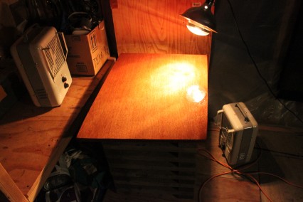
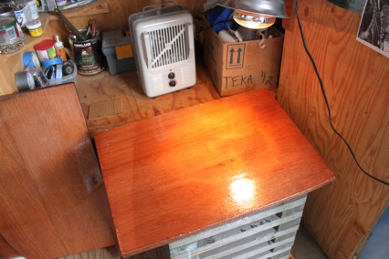
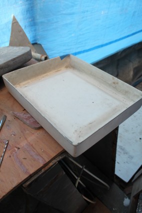
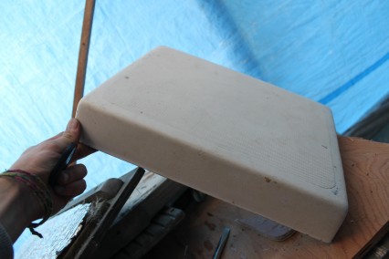
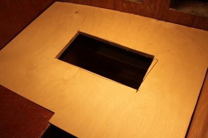
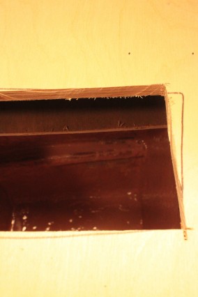
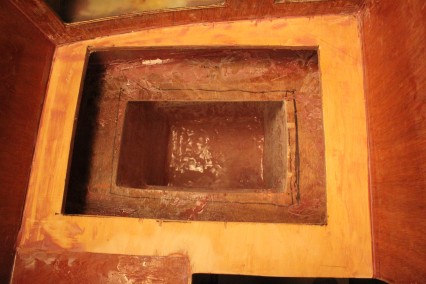
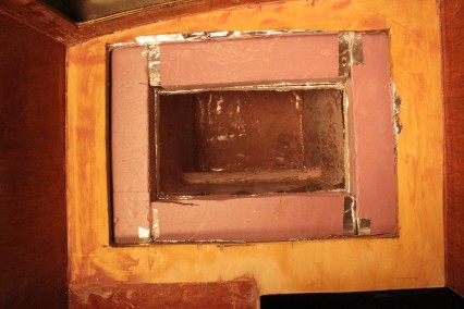
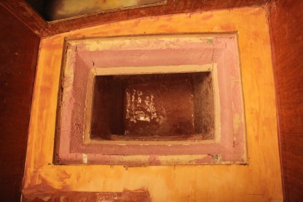
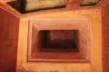
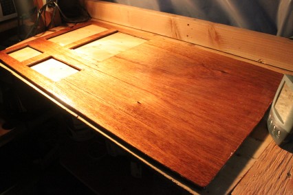
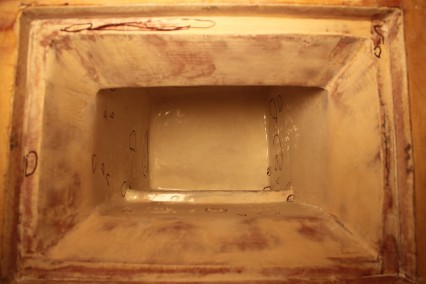
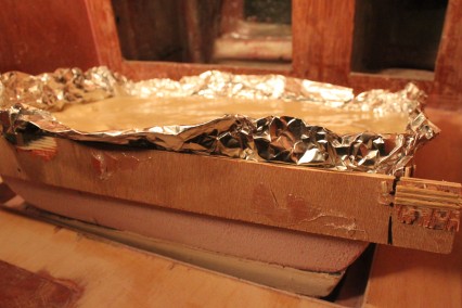
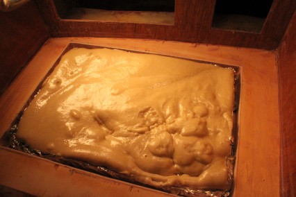
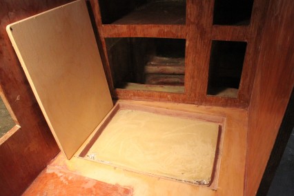
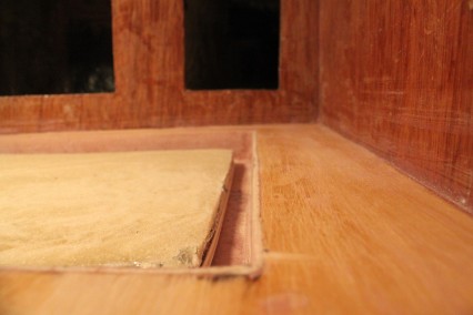
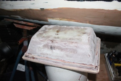
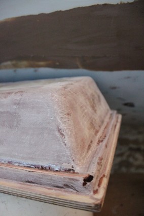
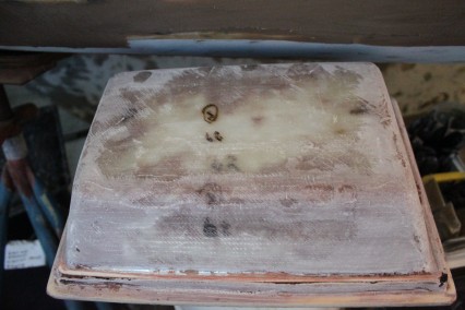
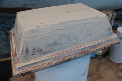
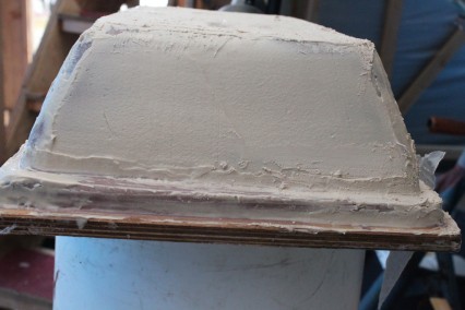
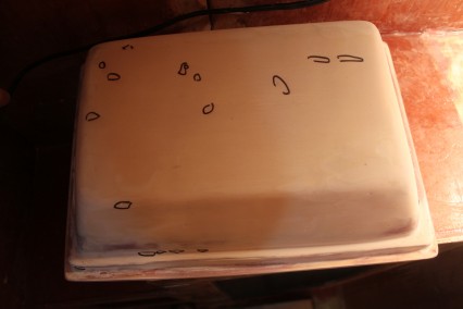
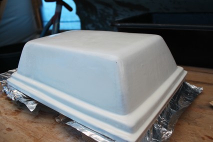
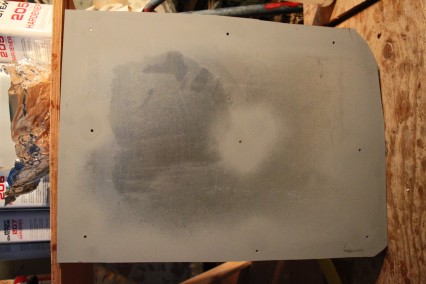
The final coats of epoxy on the icebox lid have been applied. I hope this is the last coats the lid needs, but likely after I paint the icebox I will need to do some more fine tuning of the lid as which will likely result in some more coats of epoxy here and there. Here’s an image of the last coat of white-tinted epoxy I applied to the lid:
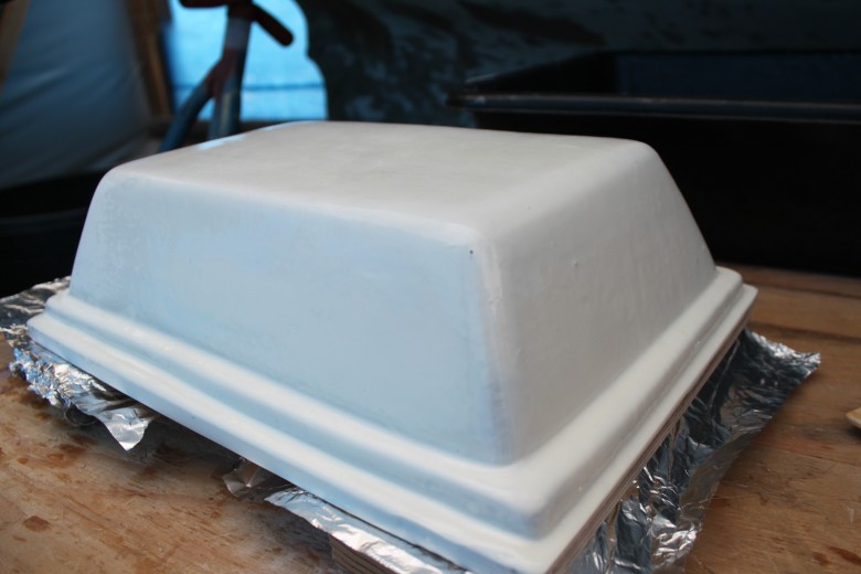
This image shows the second to last coat of white-pigmented epoxy that has been applied on the icebox lid. Nice to see something look somewhat “finished”.
July 14, 2011
The icebox lid fitting has been on hold while I finished worked on the diesel tanks. After I painted the lid with 4 coats of white pigmented epoxy, it’s hasn’t been quite fitting properly. It’s a bummer to build the lid, making sure it fits the whole way along, then once the epoxy is added it doesn’t quite fit right. While it’s a bit of a let down – no worries! – I’ll just use my trusty sanding skills to make it fit just right.
I’ve been trying to think of a way I could have planned ahead to make sure that once the icebox was painted and ready, the lid would have fit. I suppose I could have calculated the thickness of what 4 coats of epoxy equals, then subtract that from all sides of the icebox lid, but I really have no idea how I could have really measured this thickness on both the icebox lid and the icebox itself. As I find myself doing with a lot of things, I’ll just work on it until it fits to my liking. Typically this means a lot more hours invested in a project than a professional boat builder would spend, but I’m still learning and learning takes more time.
June 17, 2011
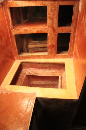
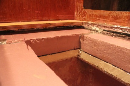
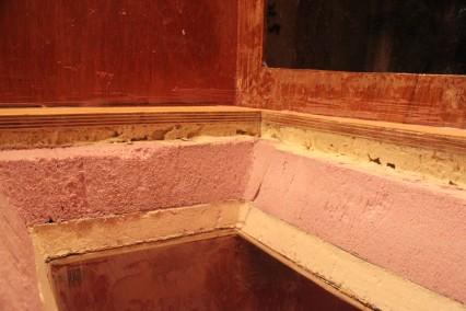
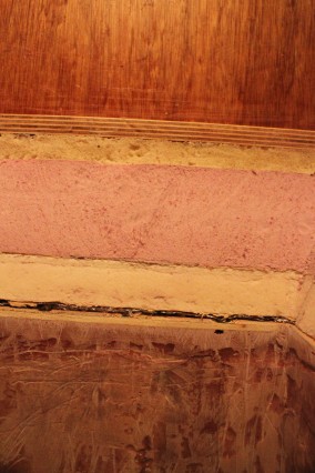
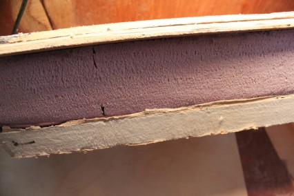
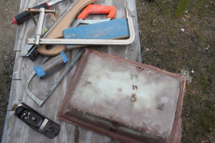
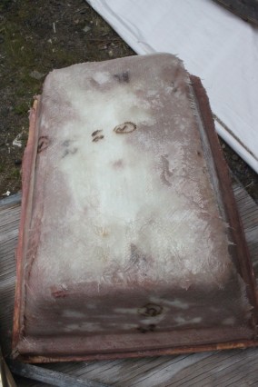
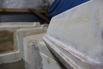
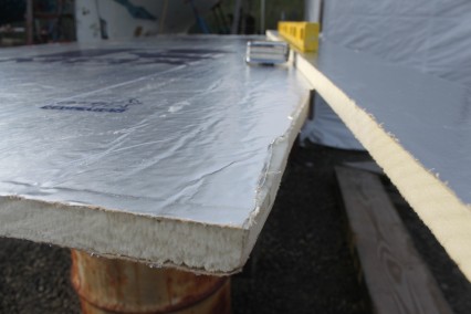
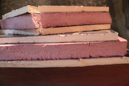
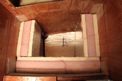
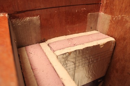
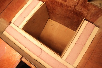
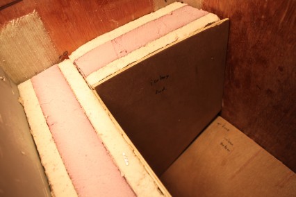
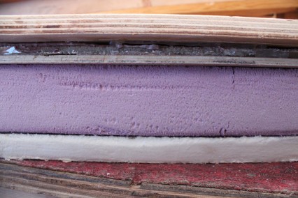
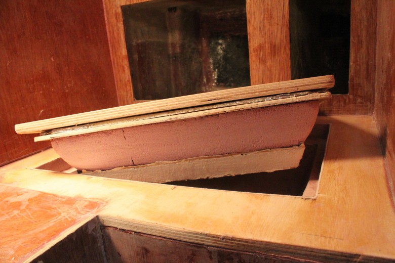
The icebox lid has taken shape gradually. The layers of the lid are as follows (from top to bottom):
- 1/2″ Russian Birch (Marine Grade)
- Spray Foam
- 1/4″ Luan
- 1″ polyisocyanurate insulation
- 2″ DOW Pink foam board
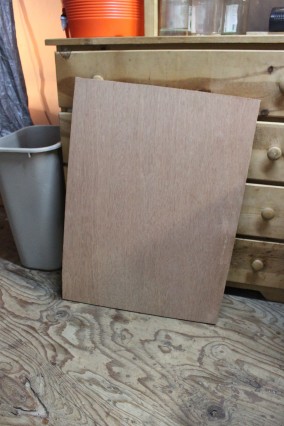
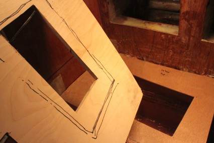
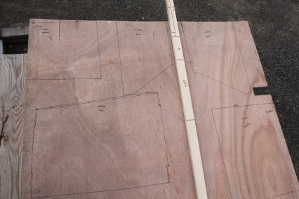
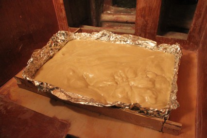
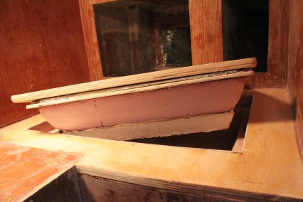
Here’s an image showing the lid prior to any fiberglassing that shows the layers I mentioned above:
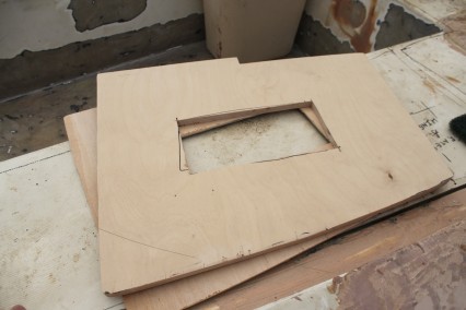
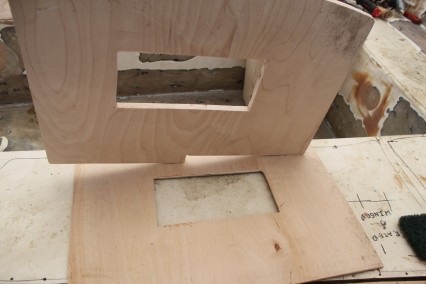
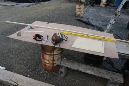
My construction steps were probably a little different than how other folks do things, but I first molded the opening to the icebox itself with foam. Then I templated and cut a piece of wood that would fill the icebox opening for the counter and used this to build a matching 1/4″ luan lid. To the luan, I attached 3″ of insulation and then shaped shaped this insulation until it fit snugly in this opening. Once the luan and foam lid fit well, I laid down some spray foam on top of the luan and molded the foam so it would support the icebox lid even with the counter. I then thickened everything together, put a layer of glass over everything and began fairing.
I’m at the final fairing stage still and probably have 1 – 2 more fairing coats before it will be smooth enough to paint.
July 14, 2011
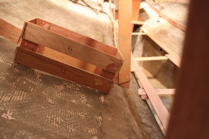
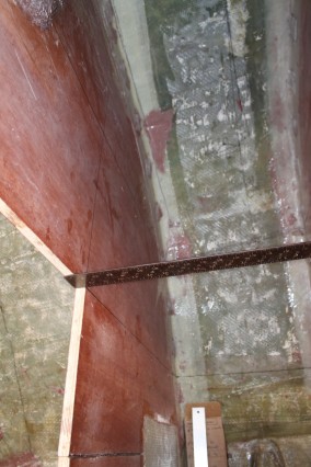
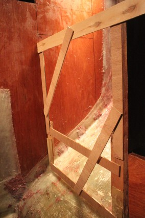
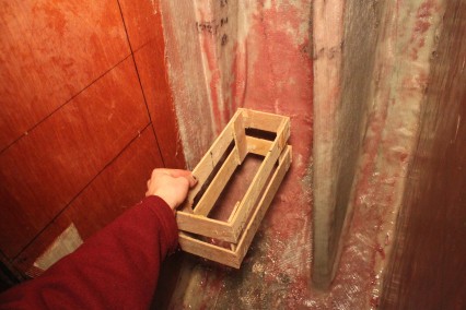
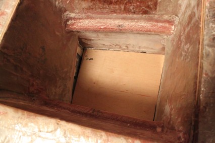
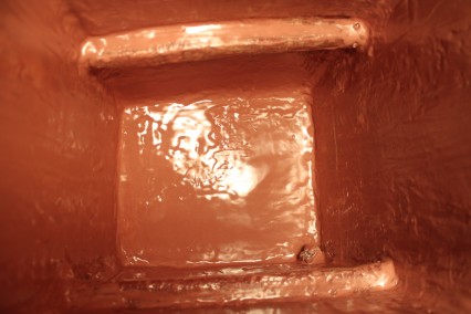
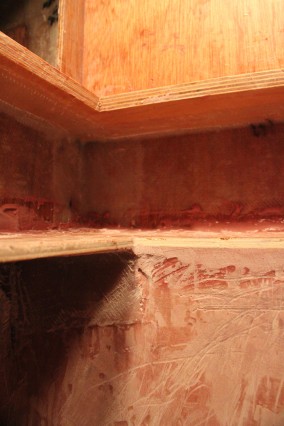
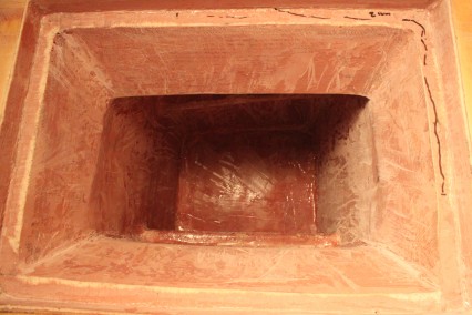
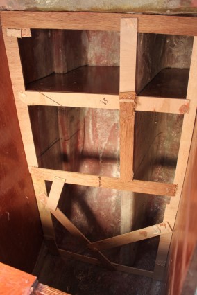
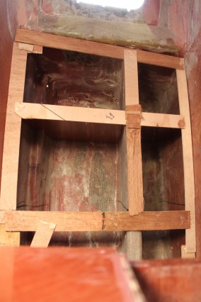
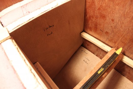
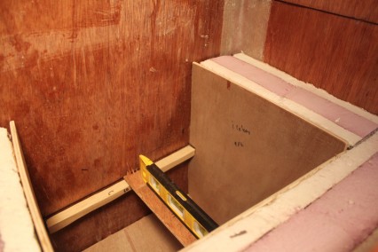
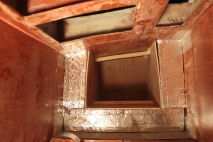
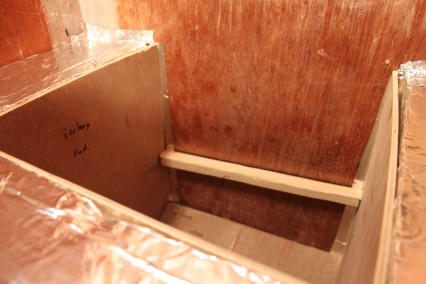
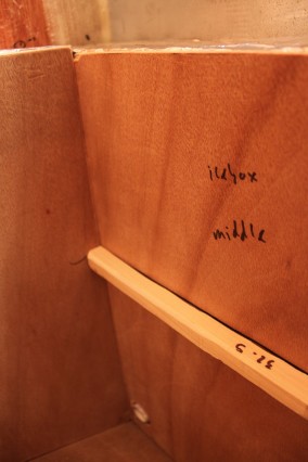
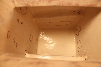
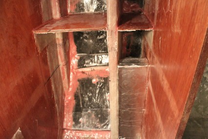
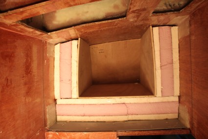
I’ve completed the installation of the cleats for the shelf that will be placed in the icebox. My plan is to install plexiglass shelves which (hopefully) can slide. If not slide, I hope they will be very easy to lift out.
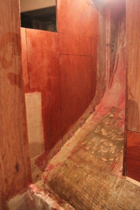
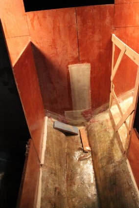
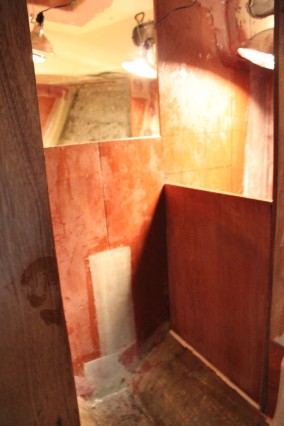
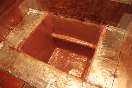
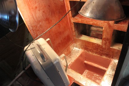
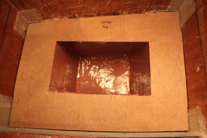
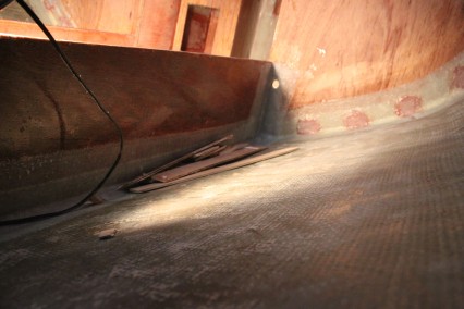
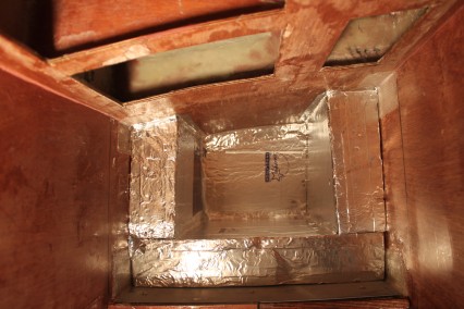
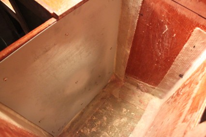
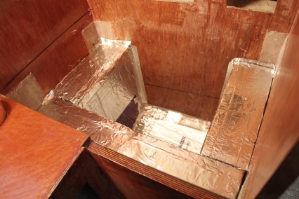
The cleats had to be parallel with the centerline, so that an icebox would fit into the lower area of the icebox. Here’s an image of those cleats:
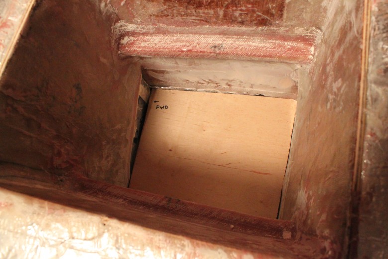
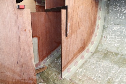
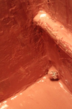
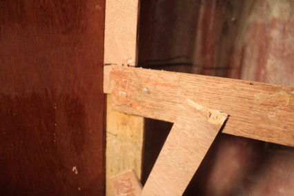
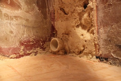
You can see the cleats installed with biaxial fiberglass. Later, I will glass over the entire box and fair the fiberglass as well. You can also notice the demolition work I had to do after the drain was plugged with epoxy.
June 17, 2011
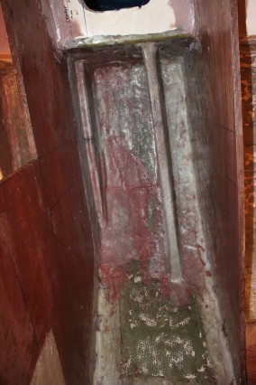
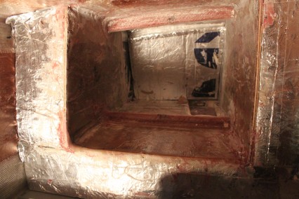
I’ve completed the basic construction of the icebox and have been working very gradually to get the box ready for paint. Since I built the icebox in place, it’s been very awkward to get the icebox faired just right and so I’ve had to do rinse-repeat sanding and fairing a number of times. I just prepped the icebox for a final fair last night so hopefully this will set the stage for painting the entire interior of the box with white pigmented epoxy.
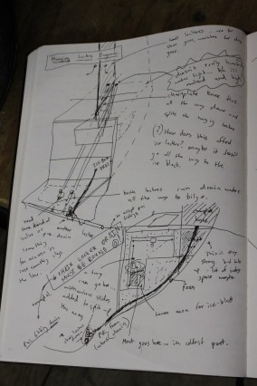
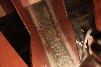
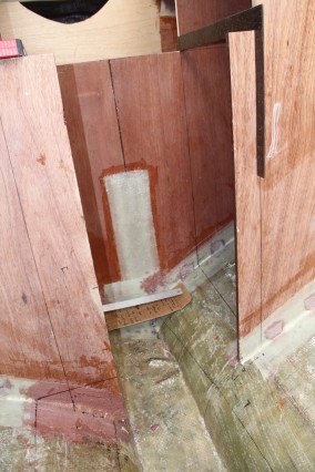
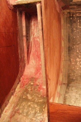
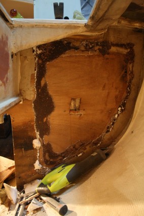
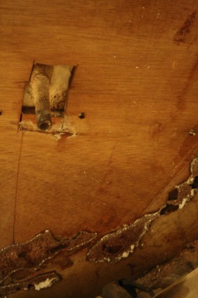
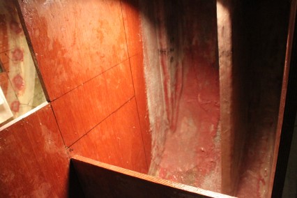
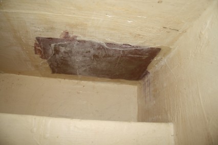
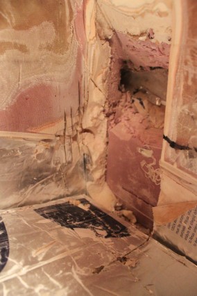
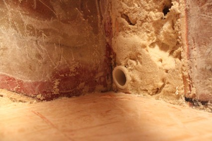
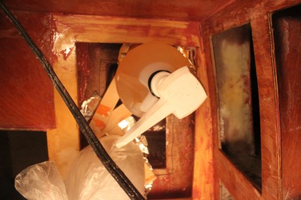
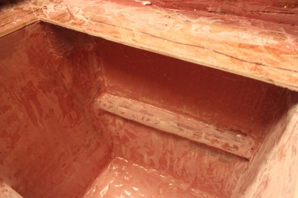
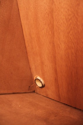
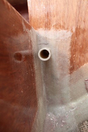
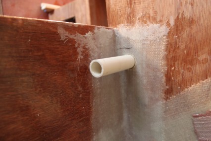
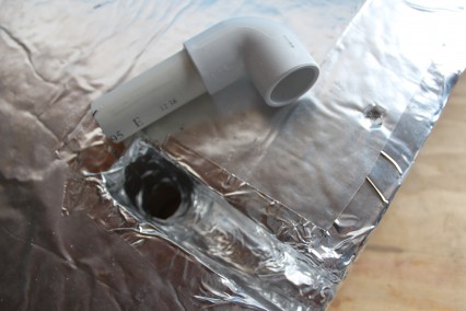
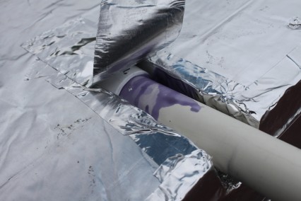
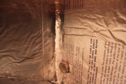
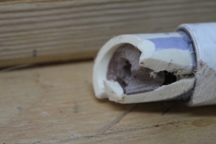
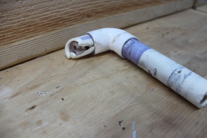
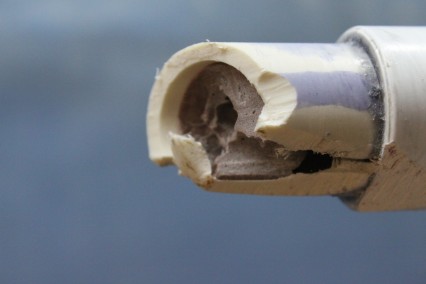
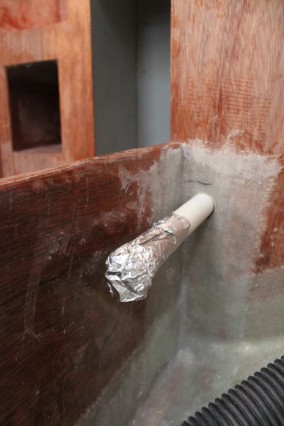
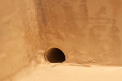
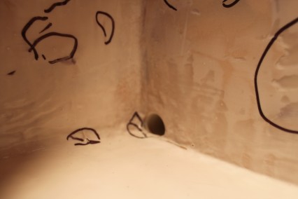
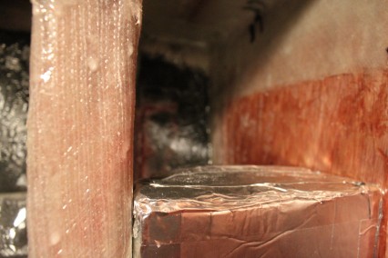
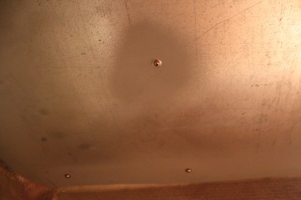
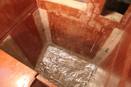
For my icebox drain, I used 3/4″ PVC that runs through the insulation, through a bulkhead and will eventually connect to the galley foot pump so I can use icebox water for rinsing dishes while at sea. Originally, the drain I installed became filled with fairing compound while I did my first round of fairing in the box. I should have considered that fairing isn’t usually a clean operation and plugged the drain while I was doing the fairing, but I didn’t and I ended up having to cut the drain out and start over again. Here’s an image of how much thickner actually ran down into the drain:
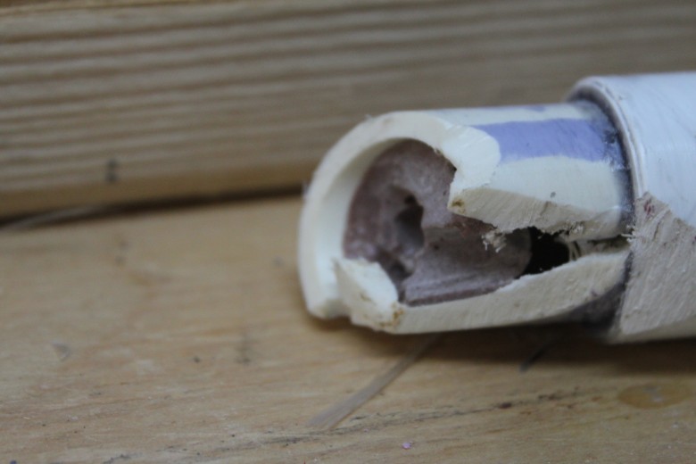
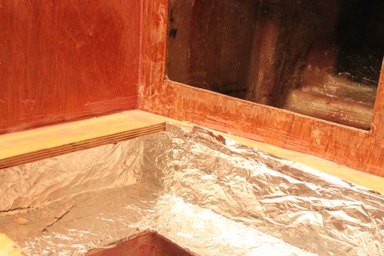
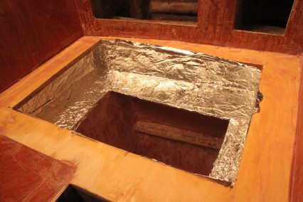
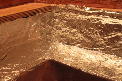
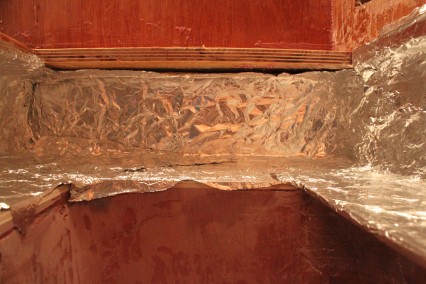
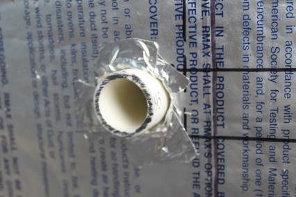
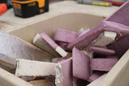
A simple oversight caused a lot of problems. I should have plugged the drain I first installed with foil. I didn’t, and when I went to fair the icebox interior, the fairing compound made it’s way into the drain. I wasn’t able to get good access to the drain to remove the stoppage, so I was forced to do some minor demolition on the icebox and rebuild the drain.
The good news is that while I had to cut out the bottom of the icebox and grind back the newly laid fiberglass I did, it also meant that I increased the volume of my icebox a bit. In the end, I just counted this as a “win” for fridge storage and will make sure to better protect my drains in the future.
August, 2009
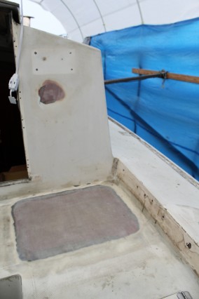
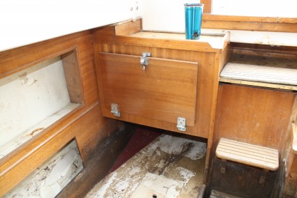
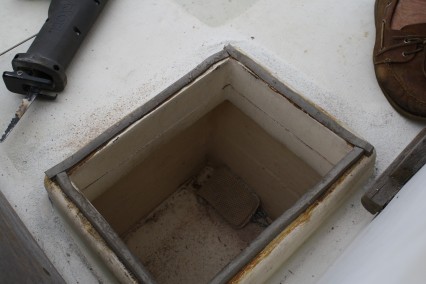
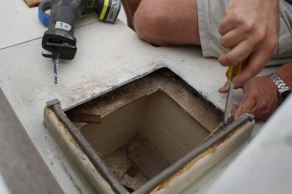
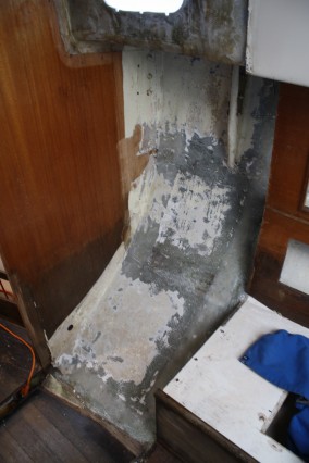
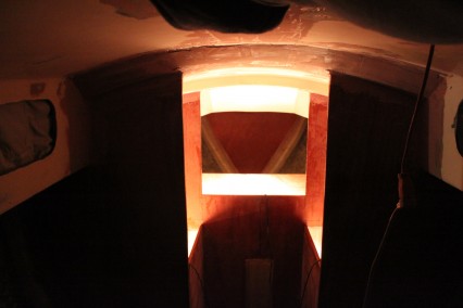
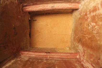
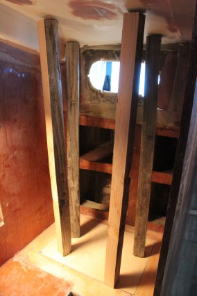
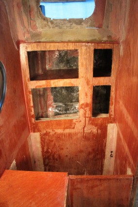
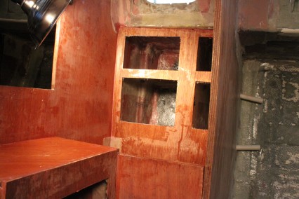
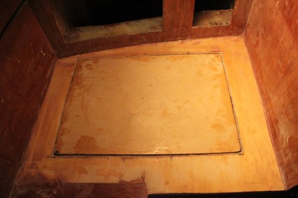
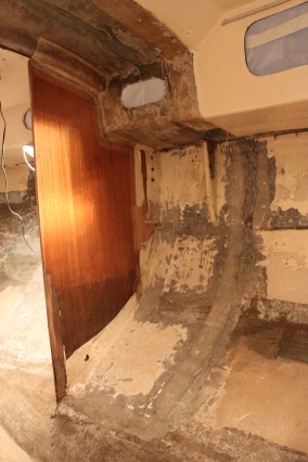
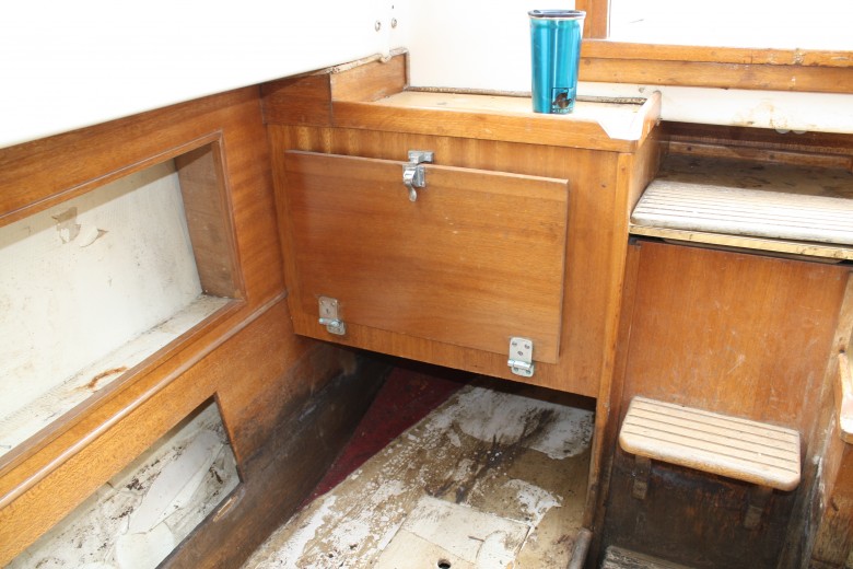
Originally, the icebox was accessible from the cockpit. I didn’t like this as it would mean a lot of air loss into the environment. I fiberglassed this hole from the deck, and will later glass the patch from below during salon construction. I will likely be moving the location of the icebox as well, but I’ll have to do some more thinking about how the interior will come together before I decide the icebox’s location. For reference, here’s what the icebox originally looked like:
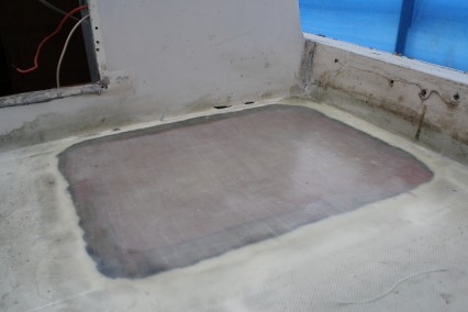
Here’s how the cockpit access patch repair was completed:
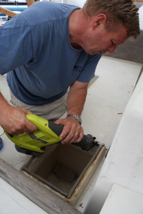
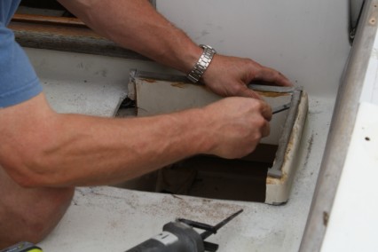
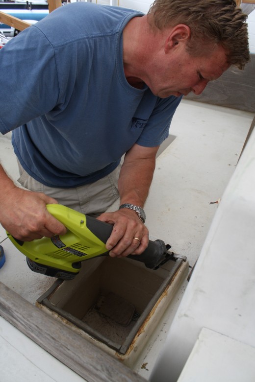
- Demolition– My dad assisted me in trimming the icebox flanges down. Later, I ground the area around the icebox opening in preparation for future fiberglassing. Here’s my dad working with a boat builders key demolition tool – a SawzAll:
- Wood Patch – With the hole ready for fiberglass, I needed a way to lay the fiberglass over the hole itself. This required thickening in place a wood patch. The patch filled the majority of the hole, however there were still some openings around the wood patch that I couldn’t get to, so I used spray foam to fill these voids.
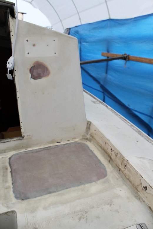
- Fiberglass– With the area prepared for fiberglass, I cut the fiberglass and epoxied on a few layers of fiberglass. I also fiberglassed the inside of the icebox and each area will receive some fairing in the future. Here’s what the patch looks like from in the cockpit:
Research
Construction
- I began laying 1″ blue board (overlapping joints) until I had the box shape that I wantedwanted . Thickness varied from 4-7 inches. Using door skin I made patterns for the new liner. The patterns were transferred to 1/4 MDO and then after a trial fit were covered with 2 layers of 4oz cloth and West Systems. A vapor barrier was added and then the ply was fit using Liquid Nails to seal the joints. A few day later I covered all of the joints with 2 layers of cloth tape and West. When all that was cured several coats of Brightside was applied. (http://www.cruisersforum.com/forums/f55/building-an-ice-box-26977.html)
- installed precut layers of fiberglass cloth on all surfaces–two layers for the three vertical surfaces, and two layers plus one layer of 24 oz. roving on the bottom and curved (outboard) side. (http://westsystem.com/ss/building-an-efficient-icebox-2/)
- Construct the outer box from ¼” marine grade plywood. If you are building to fit a specific space, adjust the outer dimensions accordingly. If you are building to a specific interior shape or volume, add the thickness of the insulation to get the outside box dimensions. Using the stitch and glue technique, temporarily join the sides and bottom with plastic wire ties. When you are satisfied with the shape and fit, lightly form fillets on the interior joints. I used WEST SYSTEM 105 Resin with 206 Hardener for this project with 407 Low-Density Filler for joints and fillets. This is plenty strong enough, sands easily, and has some insulation qualities. When the fillets have cured, cut and remove the tie wraps, and then sand the fillets smooth. Apply 3″ wide, 9 oz fiberglass tape to the inside corners of this outer box. (http://westsystem.com/ss/building-an-efficient-icebox-2/)
- A smooth fiberglass molding makes an excellent icebox liner, far better than the stainless steel liners used in the past. (http://www.cncphotoalbum.com/doityourself/icebox/improve_ice_box.htm)
- One advantage of urethane foam is that it is not attacked by styrene, so that a fiberglass/polyester liner can be laid up directly on the foam. If at all possible, do not try to do this step with the insulation in place, as it will require glassing to vertical panels, then grinding smooth and finishing. This is a nasty job. Instead, after all the insulation for the sides, end, and bottom of the box is fitted, use a marker to indicate the in- side dimensions of the box, then number the pieces of insulation and remove the innermost layer from the box. Cut several layers of light fiberglass cloth to the size and shape of the exposed inner surface of the individual pieces of insulation. You only want to glass up to the lines you marked on the insulation before removing it from the shell, rather than the entire surface of each piece.Three layers of light fiberglass cloth will make a reasonably sturdy liner that will allow you to tap into it for supports for the shelves to be installed in the box later. Be as neat as possible in your fiber-glassing to minimize the amount of finishing work required. The liner should be as smooth as possible to facilitate cleaning.If you are considering adding refrigeration at some time, you should make a liner of 1/4″ plywood to which the glass is applied, rather than glassing directly to the insulation. This will allow you to fasten heavy holding plates to the inside of the box without fear of the fastenings pulling out.Whether you glass directly to the insulation or build a plywood liner, the comer joints will have to be taped with fiberglass after the insulation panels are reinstalled in the box.Reinstall the insulation in the shell. Layers of insulation can be glued together with contact cement, silicone caulk, or polysulfide. All comer joints should be caulked with silicone or polysulfide. If a fiberglass-over-plywood liner is built, it can be attached to the inner layer of insulation with polyester epoxy, or one of the caulking compounds. If you’re really clever, you figured out where the drain will have to be installed in the bottom, then ground a small recess in the bottom insulation at this point so that the drain fitting can be installed flush with the bottom surface later on. If not, don’t worry, it just means that you’ll have to mop the last little bit of water out of the box with a sponge.With the insulation and liner in place, the inside comer joints are glassed and the entire interior given a coat of clear resin. The last bit of sanding to smooth out the taped comer joints should be done before applying the final coat of resin.Wax-free polyester resin should be used for the liner lay-up. This remains slightly tacky to the touch, but it means that it doesn’t have to be sanded between coats of resin. In addition, the polyurethane or epoxy paint that you use to finish off the inside of the box will adhere better. We don’t recommend trying to gelcoat the inside of the box. (http://www.cncphotoalbum.com/doityourself/icebox/build_icebox.htm)
- The box liner is 4 mm okoume stitch and glued together and covered with a layer of 4 oz glass inside and out. The interior was then faired to get a smooth surface. (http://www.rutuonline.com/html/refrigeration.html)
- The inner box should be tough enough to protect the insulation from hard objects such as cans, ice and solid frozen items. It must be watertight. It should be smooth with rounded inside corners for easy cleaning and sanitation (http://westsystem.com/ss/building-an-efficient-icebox-2/)
- Sand all interior fillets and apply 3″ wide fiberglass tape over all of the inside corners. Apply 6 oz fiberglass fabric on the bottom of the inner box. (Sidewalls are not covered with fiberglass fabric.) When the wet-out fabric has reached the slightly tacky cure stage, coat the interior with epoxy and 501 White Pigment. Apply using an 800 Roller Cover and a short-bristled brush for the corners. Tip off each coat with a foam bush before it begins to gel. Apply several additional coats of pigmented epoxy to the interior, waiting until the previous application is tacky. (http://westsystem.com/ss/building-an-efficient-icebox-2/)
- A new interior liner can be made with Strutoglas flexible fiberglass panels – made by Kemlite this is sold by Home Depot. The product was originally sold as a wall panel for walk in freezers. It is usually sold as a bathroom wall panel. (http://www.great-water.com/pages/Refrigeration/ice_box_design.htm)
Design
- Kick space whenever possible, there should be a toe space under the face of the box at least 3″ deep, so that it is possible to get closer to the counter. This space need be no more than about 6″ high. (source)Inside depth should be limited to what the cook can comfortably reach without standing on his or her head…The lid should be no larger than necessary to get the largest block of ice in and to provide access to the interior….Ideally, the box should be no higher than the surrounding counters, for ease of access. A counter height of 33″ to 36″ above the cabin sole is about right. Be sure that there is adequate clearance above the top of the icebox – about 18″ minimum – to make it. possible to fully raise the lid and get things in and out…The depth from the front of the counter to the inside back of the box should not exceed about 24″, less if there is no kick-space to allow you to get closer to the front of the box. this requirement can be ignored if there is access to the box from all sides….Although the first food shelf may be well above the bottom of the box when ice is used, cans and bottles usually find their way to the bottom pretty quickly. An inside depth of much more than 24″ will be a long reach for a short person…Probably the best shape of all for the cool box is a long, narrow, shallow, rectangular box. There will be less temperature differential between the top and bottom of this shape, and the ice can be distributed over a larger bottom area. The space underneath can be compartmentalized for pan storage, which always seems to be in short supply…At every step along the way, stop and think before doing anything irreversibe, as the sequence of construction is critical….For optimum performance, choose a top-opening rather than a side-opening icebox. Top packing is more efficient, and cold air won’t drain out whenever you open it. Try to keep proportions as close to a cube as possible, which will give you the most volume with the least amount of exposed surface area. (http://www.great-water.com/pages/Refrigeration/ice_box_design.htm)
- Reaching zero air leaks requires a first-class installation of the foam and tightly fitted lids with good gaskets. Many sailboat iceboxes were built with a water drain in the bottom. Since cold air falls, guess where it all goes—down the drain, carrying ice-cold water that still has a lot of Btus left in it. Plug that darn thing and put in a drip pan to catch the water if you’re using ice. (http://www.sailnet.com/forums/gear-maintenance-articles/19905-refrigeration-part-i.html)
- A good box should have a minimum (more is better) of 4 inches of good closed-cell insulation all around, including the top. The insulation should have an outer seal to prevent moisture from wicking through and eventually impairing the insulation….It should drain overboard or into a sump, but it should be looped at least once so that there is always a barrier of water standing in the drain tube. You don’t want the constantly drain cold air out of that tube, just water…Remember if it is against the hull…and if your goal is to be sailing in warm waters – add extra insulation here.
- The opening should seal well. I prefer a top-opening unit. Yes, it can be a real pain in the neck to reach down there and find the good stuff on the bottom, but refrigeration is a real pain in the neck anyway.
- The galley lighting should illuminate the insides of the iceboxes, which usually requires a light specifically located above them. (Cruising Handbook, p. 185)
- A box of about seven cubic feet is more than adequate for a boat cruising with four people. Bigger boxes mean more volume to be cooled, and more surface to be insulated. (http://www.cncphotoalbum.com/doityourself/icebox/build_icebox.htm)
- Icebox should be large enough to carry 50 lbs. of ice and still leave at least 2 cubic feet for food….5” of foam….two blocks of ice should last you up to three weeks.
- For a refrigerator box: 4 cu ft or less, use a minimum of 2 inches. 6 cu ft will need 3 inches. Bigger than 8 cu ft needs 4 inches (http://www.great-water.com/pages/Refrigeration/ice_box_design.htm)
- For a freezer: 2 cu ft or less, 4 inches minimum. 4 cu ft or less, 5 inches. Larger than 4 cu ft, 6 inches. (http://www.great-water.com/pages/Refrigeration/ice_box_design.htm)
- The bottoms of the [icebox] should be accessible to a person with an average reach. The measures also make it reasonably easy to clean the iceboxes… (Cruising Handbook, p. 185)
- Icebox lids should be close to the edge of the countertop in which they are placed. (Cruising Handbook, p. 185)
- It should not be necessary to unload the top of the refrigerator to access the bottom. If the icebox does not have a front opening door at the bottom, shelves can be designed to slide backward and forward or from side to side. if this is not possible, any shelves should at least be designed so they can be lifted out without having to unload their contents. (Cruising Handbook, p. 185)
- The bottoms of the [icebox] should be accessible to a person with an average reach. The measures also make it reasonably easy to clean the iceboxes…
- It is important to seal the drain so that it does not become a source of heat gain. The drain should lead to a container, or pump into the galley sink, but not to the bilge (it causes smells).
- The galley lighting should illuminate the insides of the iceboxes, which usually requires a light specifically located above them.
Drain
- Probable us ½ inch or ¾ PVC plumbed out of the bottom of the box with it running between the two layer of insulation I’m using. I’ll cork it from the inside also. (http://www.boatdesign.net/forums/fiberglass-composite-boat-building/built-ice-box-foam-whats-best-9164.html)
- For a drain I often simply flare a piece of copper or stainless tubing and set it into a tapered hole and bedded into epoxy. It can be stoppered with a small cork. Very simple but effective enough. Of coarse this method is for ply and glass lined boxes. (http://www.boatdesign.net/forums/fiberglass-composite-boat-building/built-ice-box-foam-whats-best-9164.html)
- Yeah that is a good method as well. I use a flush thru hull fitting for the drain to get a drain that doesn’t pool water, or if you go with a stainless liner, the metal worker at many good stainless shops will have the press mandrels to push a sink flange into the bottom sheet. (just like on a stainless lav sink) Scandvik sells the little right angle sink drains with a hose barb to carry the drainage away. Makes for an easy to clean reefer.
- Sooner or later, the icebox has to be drained. A common mistake is to install a drain that is too small in diameter, so that small food particles – which inevitably end up in the bottom of the box – can clog the hose. The drain should not be less than 1/2″ inside diameter. Nylon through hull fittings can be used as drain fittings for iceboxes. They can be recessed flush, much like through hull fittings in the hull, or they can be allowed to stand proud on the inside of the box. The only disadvantage to not recessing the fitting is that it will be necessary to sponge out the last bit of water – hardly a major problem.Now that you have a way to get the water out of the box, what are you going to do with it? Almost invariably, the bottom of the box is below the waterline, so the drain cannot be led directly overboard. The simplest solution is to fit the drain with a tight stopper inside the box, and fit a piece of hose over the drain tailpiece. When the time comes to drain the box, the hose can be placed in a bucket and the stopper removed from the drain. Since we’ve already decided not to drain the box every time a little water appears in the bottom, this type of drain system isn’t too inconvenient.If the galley sink is below the waterline – common on older, deep boats with relatively low freeboard the icebox drain can be teed into the sink drain, which either goes to a sump, in more complex boats, or to a simple overboard pump in boats without room for sump tanks. This “tee” should really be a Y-valve, so that the sink drain can be kept from backing up into the icebox in certain conditions.No matter how you decide to drain the box, a tight-fitting stopper is a must to keep cold water in the box, and warm air out. (http://www.cncphotoalbum.com/doityourself/icebox/improve_ice_box.htm)
- A 1/2″ drain at the bottom of the partitian lets the freezer share the drain with the refrigerator. (http://www.cncphotoalbum.com/doityourself/icebox/improve_ice_box.htm)
- Drains are a minor source of heat loss, but they are very convenient, especially if the icebox is built in. To install a drain, bond ¾” or 1″ PVC pipe into the sidewall, flush with the inside bottom of the box. Use a female threaded fitting on the end of the pipe flush with the outside of the box. Cut or drill a hole slightly larger than the outside diameter of the pipe. Cut the pipe to length so the fitting is flush with the outside of the box. Bond the pipe in with plenty of thickened epoxy, filling all gaps between the pipe and the box. Use a threaded plug to seal the drain when in use. Any number of plugs, draincocks or even an appropriately sized cork can work. Keep in mind the first principle of hydrokinetics -drains always plug up, plugs always leak. (http://www.cncphotoalbum.com/doityourself/icebox/improve_ice_box.htm)
- I wanted a trap in my drain to hold some cold water and prevent the cold air in the icebox from flowing out the drain. Since the amount of space was so limited, I had to improvise a trap out of miscellaneous 3/4 inch PVC elbows.
- Used a copper tube epoxied into place and a vapor loop in a hose for the drain. (Upgrading the Cruising Sailboat, p. 69)
- It is important to seal the drain so that it does not become a source of heat gain. The drain should lead to a container, or pump into the galley sink, but not to the bilge (it causes smells).
Hardware
- Install stainless steel hinges and a latch by mounting them to ¼” plywood base plates, which are bonded to the box and lid. Before fitting the hinges and hasp, place some of the ½” marble spacers in the gasket groove, and then place the lid on the box. The spacers will assure the lid is in proper alignment when fitting the hinges and hasp. ( http://westsystem.com/ss/building-an-efficient-icebox-2/ )
- Determine the hinge locations. Then fit and trim the plates about ¼” larger than the hinges and apply three coats of epoxy to exposed sides. After the epoxy cures, bond the base plates in position with thickened epoxy. Fasten the hinges with flathead stainless steel self-tapping screws that are long enough to pass through the plates into the plywood sides of the lid and box, clamping the base plates to the box and lid until the epoxy cures. Do not bond the screws or hinges at this time. (http://westsystem.com/ss/building-an-efficient-icebox-2/)
- For the latch, I used a flexible rubber draw latch with a nylon strike. There are a couple of tricks to installing the latch which, like the hinges, is mounted on a ¼” plywood base plate. Make the base plate in one piece, with the latch and strike fastened to it in the latched position (below). Position the strike so there is a bit of tension on the draw latch. Coat the plate with three coats of epoxy before blind fastening and bonding it to the base plate using stainless steel flathead machine screws from the backside. Countersink the screws flush with the back surface. After this has cured, bond the base plate, in one piece, over the joint between the icebox and lid, using thickened epoxy. Hold in place with staples or clamps until the epoxy cures. When cured, open the latch and carefully saw through the base plate at the joint. (http://westsystem.com/ss/building-an-efficient-icebox-2/)
Ice
- The “average” block of ice weighs about 25 pounds, although prepackaged blocks may only be about 10 pounds. For practical purposes – that is, not having to look for ice almost every day – a box should be capable of holding at least a 25 pound block, plus a reasonable amount of food. For cruising for more than a weekend, the box should hold at least 50 pounds of ice, plus food. Practically speaking, this means a box volume of five to seven cubic feet. (http://www.cncphotoalbum.com/doityourself/icebox/improve_ice_box.htm)
- To test your box, purchase a block of ice, weigh it, then put it in the box. Twenty four hours later, remove the block and weigh it again. By this time, the box should be thoroughly cooled. Drain the cold water, and put the block back in; The next day, weigh the block again. The amount the block melted the first day will approximate the first day’s loss of ice, while the melt the second day – which should be less – will give you an idea of the ice use on succeeding days after the box temperature is stable. (http://www.cncphotoalbum.com/doityourself/icebox/improve_ice_box.htm)
- Sliding shelves that give quick access to all levels of the box are a partial solution, but the best solution of all is to simply not open the box as frequently. Instead, keep a separate cooler full of ice and beverages, which the crew can get into at will. The cooler can be lash- ed to the mast, stowed behind the companionway ladder, or chocked down on the cabin sole, and it need not be particularly large. A simple 48 quart Igloo cooler, costing about $50 and occupying a little over two cubic feet of space, will be adequate as an auxiliary icebox for a boat with a crew of six or less. You’ll be amazed at how much longer ice lasts if the box is opened less frequently. (http://www.cncphotoalbum.com/doityourself/icebox/improve_ice_box.htm )
- Warm things put into the box carry heat in with them. Load a case of soda into the box when it’s 75 degrees outside and 35 degrees in the box, and the math looks like this: 24 cans at 12 ounces per can equals 288 ounces, or 18.72 pounds, of liquid with a 40-degree temperature differential—18.72 times 40 degrees equals 749 Btus. The more often you load the box, the more heat you put in. (http://www.sailnet.com/forums/gear-maintenance-articles/19905-refrigeration-part-i.html)
- Click here to see an icebox leakage chart
- Bruce says his studies show that ice melts about 15% faster if standing in water. (Upgrading the Cruising Sailboat, p. 70)
- For maximum efficiency, the ice should be at the top of the box, rather than the bottom. This is not practical in most cases, and the ice ends up dumped in the bottom, sliding around in a swamp of cold water. Instead, raise the ice slightly off the bottom by adding an ice shelf. This is easily done by adding cleats to the inside of the box, about 2″ above the bottom. The cleats should be teak strips, about 1″ square, which can be secured to the sides of the box with stainless steel self tapping screws. Bed the cleats thoroughly with silicone sealer, and use screws no longer than necessary to go through the cleats and the fiberglass liner. (http://www.cncphotoalbum.com/doityourself/icebox/improve_ice_box.htm)
Lid
- The opening lid to the icebox is a key detail. It must be as well insulated as the rest of the box, and should be gasketed. If the boat is intended for offshore sailing, the lid should be hinged and equipped with a latch, to keep things in place in case of a serious knockdown (http://www.cncphotoalbum.com/doityourself/icebox/build_icebox.htm)
- Insulation and lining for the top can be constructed in much the same way as the rest of the box, with one exception. The best way to make the joint between the lifting lid and the rest of the top is to finish both the edges of the lifting lid and the top with solid teak. These can be match- bevelled or step-lapped to form the joint the lifting lid will rest in, on the side opposite the hinge. If the lid is hinged, a bevel must be usce which is radiussed to the arc the lid will swing in when opened. Now you see why a drop-in lid is less complicated. (http://www.cncphotoalbum.com/doityourself/icebox/build_icebox.htm)
- The lid is a slab of the 2″ insulation covered on all sides with ¼” plywood. To keep the lid perfectly flat, clamp it to a flat surface when bonding the sides, top, and bottom to the insulation. Cut the foam insulation ½” smaller than the top dimensions of the box. Cut and fit 2″ wide strips of plywood over the sides of the insulation. When finished, the sides of the lid should be flush with the sides of the box. Bond the plywood to the foam with epoxy thickened with 407 Low-Density Filler and allow to cure. Cut the plywood top and bottom pieces slightly larger than the wood-sided insulation slab. Bond them to the slab. Use weights about the perimeter and the center so the lid cures flat against the surface. To insure a perfect fit between the lid and box, I applied a layer of epoxy, thickened with 407 filler, around the top of the box. I placed a sheet of plastic over the epoxy, then set the lid in place over the box. A couple of weights placed on the lid helped the epoxy conform to the exact contour of the lid. When the epoxy cured and the plastic was removed, I had a perfect lid-to-box fit. Note the drain pipe at the bottom of the box. (http://westsystem.com/ss/building-an-efficient-icebox-2/)
- I installed the plywood top frame of the box, leaving a 1/2 inch margin of glassed-over insulation exposed, which the icebox lids would rest on. I then cut and fit the insulation for the lids and attached the pieces to the plywood lids with hot-melt glue. Where the two lids met, I staggered the insulation, to minimize air leaks and triple-checked that once the lids were installed I would be able to lift the inboard lid out of the box without disturbing the outboard one. (http://www.dasein668.com/projects/winter0405/icebox)
- To install the icebox lid, I installed some hardwood cleats along the sides of the opening to support the top. I left some clearance for some gasket material that will be installed later. With a little fine tuning on the size of the hatch, it fit tightly into the opening. In the center of the lid, I routed a space for a small flush pull ring, one that I had on hand.
- Generally recommends a lid thickness of 4 inches. The calculated effect will be to reduce the total efficiency gain by 2.8%, but the real effect will be smaller because the top of the box is generally the warmest, so the temperature differential is the smallest here. Don’t shave lid below 3 inches. (This Old Boat, p. 381)
- Great walkthrough of building the lid on pages 381 – 384 of This Old Boat
- Icebox lids are best hinged. The variety that slides does so at the most awkward time. (From a Bare Hull, p. 36)
- If not secured in place with a hinge, it too needs locking down (Cruising Handbook, p. 121)
- Icebox lids should be close to the edge of the countertop in which they are placed. (Cruising Handbook, p. 185)
- The seal between the lid and the box is an important part of the icebox’s thermal efficiency. You can copy the detail of existing coolers or design the seal around a specific type of weatherstripping, as long as it is airtight. I used a basic, but reliable design that incorporates a ½” diameter round gasket material made of ETFE rubber. I built a channel on the top edge of the box and a mating channel on the underside of the lid to accommodate the gasket. The alignment of the mating channels is critical. (http://westsystem.com/ss/building-an-efficient-icebox-2/)
- To make the channels, fabricate eight, two-piece corner sections out of ¼” plywood and bond one pair on each of the box’s corners (below). Separate the pieces by a ½” wide channel for the gasket. When cured, place sections of plastic bags (to prevent inadvertent adhesion) over corner sections and place waxed ½” diameter marbles or ball bearing spacers in the corner slots. Now place the matching pairs of corner sections for the lid over corner sections on the box top (with the plastic in between). Coat the top surfaces with thickened adhesive to be sure they are tight against the ball bearing spacers. Then lower the lid onto these corner sections, keeping the lid aligned with the sides of the box. Allow the epoxy to cure. When cured, remove the lid. The gasket slots at the corners of the lid and box should be perfectly aligned when the lid is in position on the box. ( http://westsystem.com/ss/building-an-efficient-icebox-2/ )
- Left-Detail of the channel on the top edge of the box. This channel and a mating channel on the underside of the lid will accommodate the rubber gasket. Right-To make the channels, I began by fabricating eight, two-piece corner sections out of ¼” plywood and bonded one pair on each of the box’s corners. ( http://westsystem.com/ss/building-an-efficient-icebox-2/ )
- Now cut and fit the sixteen straight sections of ¼” plywood necessary to fill in between the corner sections (one on each side of the slot on each side of the box and lid). Bond these pieces in place. When everything has cured, sand all of the joints and slots smooth. Break all sharp edges and fill any gaps or low spots with fairing compound. When cured, sand everything to your satisfaction. Apply three coats of white pigmented epoxy to the inside of the lid, including the gasket channel on the lid and on the top of the box. (http://westsystem.com/ss/building-an-efficient-icebox-2/)
- After painting, carefully bond the gasket into the icebox slot with thickened epoxy. Apply adhesive to the slot only and place the gasket in position, holding it down with a piece of plywood and light weights. After the epoxy has cured, replace the lid and install the hinges. Align the hinges with the screw holes in the base plate. Wet out the holes with epoxy before installing the screws. Apply a fillet of flexible sealant to the mating slot in the lid and let it dry thoroughly before closing the lid. The ½” gasket should form an airtight seal against the sealant in the lid slot. (http://westsystem.com/ss/building-an-efficient-icebox-2/)
Shelf
- The ice shelf itself can be teak grating, available through mail order catalogs, or can be made up from plywood – sealed with epoxy resin after large drain holes are drilled through it – or sheet acrylic. Sheet acrylic (plexiglass) is superb for icebox shelves, since you can see through the shelf to the layer below. (http://www.cncphotoalbum.com/doityourself/icebox/improve_ice_box.htm)
- A small lip on the top of the ice shelf will keep the ice from sliding off when the boat is under way. Once again, a strip of teak can be used to make this lip (fiddle), and it serves the additional function of stiffening the shelf – partitularly important when thin sheet acrylic is used. Do not drain the melted ice from the icebox. A mass of cold water is a good heat sink, and will aid a lot in keeping the box cool. Drain the water only when all the ice has melted, or when it is necessary because you are going sailing and don’t want water sloshing over the contents of the box. (http://www.cncphotoalbum.com/doityourself/icebox/improve_ice_box.htm)
- The next set of shelves should be just high enough above the ice shelf to clear the block of ice. About 10″ should be right. Once again, attach a pair of teak cleats to the inside of the box and fabricate a shelf. The shelf should not be the full length of the box. It should be short enough to allow ice to be loaded past it onto the ice shelf. If you want, you can make a short shelf to drop into position at this level after ice is loaded. This first level above the ice should be used for items that must be kept very cool to keep from spoiling, such as meat (which should be kept in sealed plastic containers so it won’t leak), and milk. (http://www.cncphotoalbum.com/doityourself/icebox/improve_ice_box.htm)
- If there is room above this level, add another set of cleats and another shelf. If the shelves are not made full length, taller items can be stored on lower shelves without interferring with the shelf above. The more shelves you can put in, the more you can get into the box without it becoming a swamp. (http://www.cncphotoalbum.com/doityourself/icebox/improve_ice_box.htm)
- It is important that all shelves be provided with holes to allow air to circulate through the box, and never store highly perishable items at the top of the box, where it will be warmest. (http://www.cncphotoalbum.com/doityourself/icebox/improve_ice_box.htm)
- Used plexiglass fiddles as well as created a slated shelf for the ice at the bottom. (Upgrading the Cruising Sailboat, p. 69)
- It should not be necessary to unload the top of the refrigerator to access the bottom. If the icebox does not have a front opening door at the bottom, shelves can be designed to slide backward and forward or from side to side. If this is not possible, any shelves should at least be designed so they can be lifted out without having to unload their contents. (Cruising Handbook, p. 185)
Comment Form